Normally, when a flow of current is there in a conductor then there is always a query whether it is a neutral otherwise a phase. For this, an electric tester is used to check the wire. For instance, when we check the two terminals of the batteries, one acts like a positive and the other one works like a negative terminal. It is known as a DC supply. But here, the flow of current includes only single way which does not rotate. In AC supply, the direction of current is reversed for each cycle because the current direction is not constant here. Hence, for the operation of any device polarities of its terminals must be known for proper connections. For example, if proper connections are not made in a house without undergoing a polarity test, it may result in a short-circuit. So, to avoid such instances, we conduct a polarity test for every device before its operation.
What is the Polarity Test?
Definition: It is a test conducted on both the primary and secondary windings of a transformer and also to know the direction of the current. It helps in inter-connecting the primary winding and secondary windings in the case of the parallel operation of the Transformer. A polarity check done by using an electrical tester is shown in the figure below.

Polarity Test
Why do a Polarity Test?
The importance of the polarity test is that by knowing the polarity of different windings we can be able to avoid short-circuits while parallelly operating the transformers.
To meet peak demands, the transformers are connected in parallel to operate. For the parallel operation of the transformer, the polarity of the transformer windings must be known i,e both primary and secondary winding.
The primary winding having a positive terminal should be connected to the positive terminal of a primary winding of the other transformer. Similarly, secondary winding having the same polarity terminals should be connected.
If the primary winding having a positive terminal is connected to the negative terminal of a primary winding of the other transformer. Then, the short circuit of the winding takes place which damages the entire device. So, this is the reason why a polarity test is done on the transformer f0r proper parallel operation.
Polarity Testing Methods?
By using a multimeter
The voltage at different terminals is found by a multimeter. The multimeter has two probes I,e Red and black. The red probe is inserted to the Line and the other to the neutral if the pointer shows any deflection we can conclude it as a Line (L). If not check by connecting the probes to the other terminals one after the other and observe the deflection. The multimeter type method of finding the polarity is shown in the figure below.
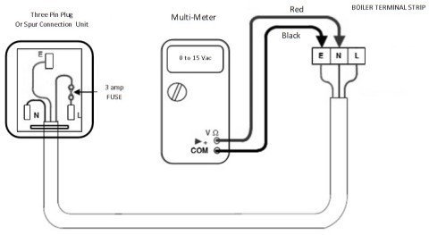
Mains Voltage Polarity Test
By knowing the resistance value
One can find the resistance of the windings and can conclude the polarity. The Earth wire has a lower resistance compared to the Line. Earth wire has to maintain low resistance compared to the Line (L) to divert surge currents in the case of a short-circuit.
Two Types of Polarity Testing of Transformer :
- Additive, and
- Subtractive
Additive Polarity
The voltmeters V1 and V2 are connected across the primary and secondary windings of the transformer. The voltmeter V1 measures the voltage across the primary winding whereas voltmeter V2 measures the voltage across the secondary winding respectively. Apart from these two voltmeters, a third voltmeter V3 is connected across both the windings I,e primary winding and secondary winding. If V3 reads voltage as the summation of both V1 and V2 then, it is an additive type.
The polarity of the primary winding and the secondary winding is different. The terminals A1 and B2 have the same polarity whereas A2 and B1 have the same polarity. The figure which explains the Additive type polarity is shown in the figure below.
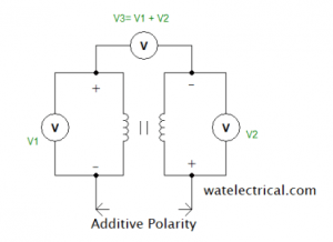
Additive Polarity
Subtractive Polarity
The voltmeters V1 and V2 are connected across the primary and secondary windings of the transformer. The voltmeter V1 measures the voltage across the primary winding whereas voltmeter V2 measures the voltage across the secondary winding respectively. Apart from these two voltmeters, a third voltmeter V3 is connected across both the windings I,e primary winding and secondary winding. If V3 reads voltage as the difference of both V1 and V2 then, it is as subtractive type.
The polarity of the primary winding and the secondary winding is the same. The terminals A1 and A2 have the same polarity whereas B1 and B2 have the same polarity. The figure which explains the subtractive type polarity is shown in the figure below.
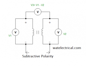
Subtractive Polarity
Practical Procedure for Testing of Transformer
Apparatus required for the practical testing of the transformer are auto-transformer, voltmeters, and a transformer.
Practically connect the primary winding of the transformer to an auto-transformer. The practical working figure of a polarity test on the transformer is shown in the figure below.
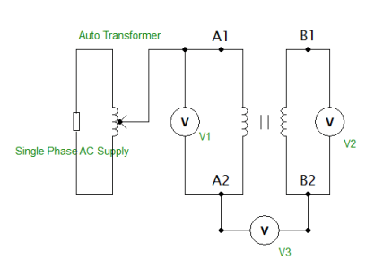
Practical Polarity Test Diagram
- Connect the voltmeter across the primary winding and the voltmeter across the secondary winding. The third voltmeter is connected across the two windings.
- Slowly vary the auto-transformer to its rated value, we observe the voltmeter readings begin to change.
- Note all the readings of voltmeters. From the values of voltmeters, we can able to conclude the polarity whether it is additive or subtractive.
- If the reading of the third voltmeter is the addition of both voltmeters then, it is an additive type.
- If the reading of the third voltmeter is subtractive of both voltmeters then, it is a subtractive type.
Precautions
- Check the practical connections are not loose.
- Do not the wire while operating.
Polarity Test of Lighting Circuit
Polarity check of lighting circuit is done by using a Megger. While using megger, check its working condition by shorting both the probes of megger it denotes zero resistance as it is shorted. The internal resistance of the winding should be high in the case of proper working.
For Testing Lighting circuit, connect one probe to the one end of the bulb and the other probe is connected to the Line with switch (SW) kept open. The pointer of megger deflects to the high resistance valve with SW OFF.
If the switch SW is ON, then the pointer of megger shows less resistance value. From this, we can conclude that the polarity of the lighting circuit is correct.
If the polarity is not correct the pointer shows zero resistance from which we can understand that there is a mistake in the connection circuit.
Please refer to this link to know more about Megger Test.
Thus, we can conclude that the polarity test is conducted to protect any device from misconnections which may lead to the damage of the equipment. In this article, we have discussed what is a polarity test, importance, methods used to test polarity. Here is a question for the readers, what is the difference between additive and subtractive polarity?
Picture Credit