A power supply is used to change the electric current from a source to the voltage, frequency & current to power the electric load. Sometimes these are called electric power converters. Power supply is classified into two categories; AC & DC power supply. We know that AC power is more economical and it can be used for transmission thus most of the electrical devices or machines run on AC power. However, the typical frequency & voltage supplied by the power stations are not good enough to drive Industrial machines. So in such situations, we use inverters and converters for changing one form of power supply to another form like different current rating frequency rating or voltage rating. A Cycloconveter is a converter that changes AC power from one frequency to an adjustable frequency AC power. This article provides brief information on cycloconverter, its types, working, and its applications.
What is a Cycloconverter?
A cycloconverter definition is; a device that changes a stable voltage, constant AC frequency waveform to a different frequency AC waveform. This can be achieved by synthesizing the o/p waveform from the AC supply segments. Cycloconverter is used in specialized systems wherever exact output frequency & low harmonic distortion control is crucial.
Generally, a cycloconverter is a one-stage frequency changer which means the input AC supply is changed directly to variable frequency o/p using power electronic switches like thyristors. These are turned ON & OFF to synthesize changeable frequency AC output. The input power of the cycloconverter is fixed AC voltage with a particular frequency but the output of this device is variable frequency & variable voltage which is controllable.
A cycloconverter device is not the same as an AC voltage controller because a fixed input AC voltage is changed into variable AC voltage without changing frequency. In the cycloconverter, the input AC supply frequency is changed.
Cycloconverter Working Principle
Cycloconverter works by synthesizing the necessary output AC waveform by selecting and changing the appropriate input AC voltage segments. This is accomplished by using power semiconductor switches like thyristors which selectively connect or disconnect separate parts of the input waveform to produce the preferred output waveform.
A cycloconverter works in two modes; rectification & inversion. In rectification mode, a positive input voltage half-cycle can be transmitted throughout the cycloconverter to produce a positive o/p voltage. In the inversion mode, the negative half input voltage cycle is passed to produce a negative o/p voltage. The cycloconverter can form a stepped output waveform including a different frequency as compared to the input waveform by properly adjusting thyristors firing angles.
It must be noted that these devices do not need any energy storage components like capacitors or inductors to work properly. But, the complexity of the control circuitry & number of power switches required might increase the total size & expense of the cycloconverter.
Cycloconverter Equivalent Circuit
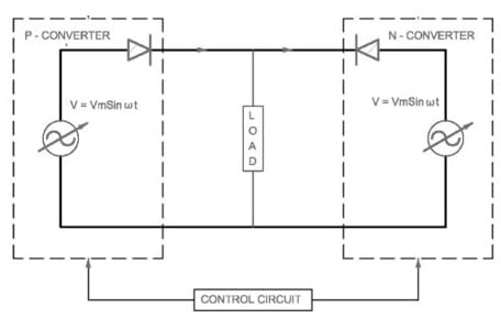
The cycloconverter equivalent circuit is shown below. This circuit is simply made with two converters where one converter functions as a P converter or positive converter & second converter functions as a N converter or negative converter. Both converters’ firing angles can be set for:
αP +αN = π
Where;
‘αP’ is the positive converter’s firing angle.
‘αN’ is the negative converter’s firing angle.

Cycloconverter Circuit
The two P & N converters’ firing angle is set to change the o/p frequency to either low or high. These converters are built with a series of connections of diode & variable alternating supply together. So these converters’ output voltage becomes equivalent within the two converters of the perfect cyclo-converter.
In this cyclo converter, the power either supplies from the connected load to the converter (or) to load by simply controlling the firing angle of every converter.
These two converter’s unidirectional property provides the result of the P converter working within a positive half cycle of alternating supply & N converter functioning in a negative half cycle of alternating supply that is given to it like input. It is independent of the phase between load voltage & load current.
Types of Cycloconverter
Cycloconverters are available in two types step up and step down which are discussed below.
Step-Up Cycloconverter
This type of cycloconverter provides a higher output frequency as compared to the input frequency through line commutation. This cycloconverter needs the default frequency which is < 50Hz. In addition, this converter needs forced commutation which improves the circuit complexity.
Step-Down Cycloconverter
This kind of cycloconverter provides a lesser output frequency as compared to the input frequency. So these converters work using natural commutation, thus these are very simple to design and operate. Further, this cycloconverter is classified into three main types; single phase to single phase, three phases to single phase, and three phases to three phase converters which are discussed below.
Single-Phase to Single-Phase Cycloconverter
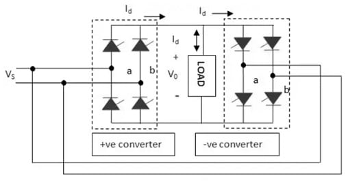
Single phase to single phase converter diagram is shown below. This circuit includes full wave converters which are connected back to back. The cycloconverter operation follows as;
If we want to obtain the output voltage as one-fourth of the input voltage then in the first two input voltage cycles the positive converter works and provides the current supply to the connected load. After that, the input voltage will be rectified. In the next two cycles, the negative converter operates & provides the current supply to the connected load in the reverse direction. When one converter is in operation, the other converter will be disabled. Thus, there is no circulating current between these two converters.

Single to Single Phase Cycloconverter
Three-Phase to Single Phase Cycloconverters
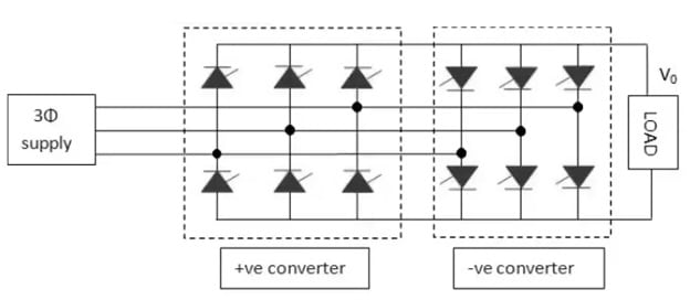
The three-phase to single-phase cycloconverter diagram is shown below. This cycloconverter works in four quadrants +V, +I, -V, and -I in two modes; inverting & rectifying. The two +V and +I quadrants are in rectifying modes whereas –V and –I quadrants are in inverting modes. Here, a positive converter provides a positive current & negative converter provides a negative current to the connected load so, that one converter will work at a time.

Three Phase to Single Phase
Three-Phase to Three-Phase Cycloconverters
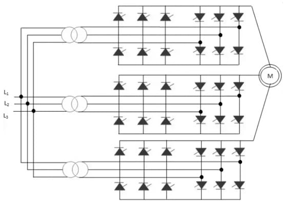
The three-phase to three-phase cycloconverter diagram is shown below. This type of converter is formed with three 3-phase to single cycloconverters connected to the connected load. This converter is utilized in AC machine systems. The two basic configurations used in this converter are; delta & wye. These converters’ output is connected in delta & wye. The output voltage phase is a shifter with 120 degrees.

Three Phase to Three Phase
Control Strategies
Controlling a cycloconverter is dangerous for reaching the suitable frequency, RMS output voltage & also guaranteeing overall efficiency and performance of the system. To manage the cycloconverter functioning, several control systems have been invented. Some of the most common control strategies of cycloconverter are discussed below.
Phase-Controlled Strategy
This is the most basic and widely used control mechanism in cycloconverters. This strategy involves changing the frequency & RMS output voltage by modulating the thyristors’ firing angles in each converter group.
This firing angle can be controlled by the preferred output voltage and the input voltage. So this control strategy is very simple to design and it provides suitable performance for a broad range of applications. The main drawback of this is, that it can cause harmonic distortion within the output waveform, so it decreases the efficiency & power quality of the system.
PWM Control
PWM control strategy provides better control above the frequency, RMS output voltage, and improved harmonic performance as compared to phase-controlled methods. The output voltage can be changed within PWM control by changing the output pulse width that is formed by changing thyristors firing angles. This strategy has the potential to decrease harmonic distortion & improve power quality. However, it requires more complex control algorithms and faster switching devices.
Vector Control
It is a complicated control strategy mainly for three-phase systems. So this strategy includes changing the values from three-phase AC into a two-dimensional vector representation that allows for very simple & efficient management of the frequency & output voltage. This control strategy enhances dynamic performance & also decreases the harmonic effect on the system. However, it requires more complex control algorithms as well as processing power as compared to other solutions.
Direct Torque Control
DTC or digital torque control is a very efficient control strategy that mainly focuses on manipulating the torque & flux of the motor directly instead of changing the frequency & also RMS output voltage. This control can achieve faster & more precise motor control by controlling these variables directly, thus it results in enhanced efficiency & performance.
The direct torque control strategy is very effective in some applications that require quick and precise torque control like; robotics, electric cars, etc. This control strategy requires more difficult control algorithms and also high-speed digital signal processing abilities.
Characteristics
The characteristics of a cycloconverter include the following.
- The main characteristic of a cycloconverter is its capability to provide changeable output voltage & frequency that it makes it used in induction heating & motor speed control.
- Cycloconverters are reliable and robust because of their minimum utilization of semiconductor devices, so they decrease the risk of component breakdown.
- They exhibit less harmonic distortion, improve power quality & decrease electromagnetic interference.
- Cycloconverters have less power factor as compared to other types of converters
- The frequency & amplitude of the converter’s o/p voltage are changeable.
- The three-phase cycloconverter o/p to i/p frequency ratio should be below than 1/3rd of circulating current mode cycloconverter (or) 1/2nd of blocking mode CCVs.
Advantages & Disadvantages
The advantages of Cycloconverter include the following.
- Cycloconverter changes electrical power directly between various frequencies exclusive of an intermediate DC stage.
- This device generates output waveforms with less harmonic content which is helpful where reducing harmonic distortion is dangerous for the correct working of connected equipment.
- Its operation is low speed and smooth.
- Cycloconverter is well suited in applications where variable AC motor speed control is required. They can change the frequency of output power smoothly to control the connected motor speed.
- These are reliable and robust when designed & implemented properly.
- Its frequency conversion ability can decrease stress on components and also provides long-term system dependability.
- These devices have very simple designs as compared to other types of converters which have rectification & inversion processes.
- These are very simple, so they improve reliability and save costs in some applications.
The disadvantages of Cycloconverter include the following.
- Cycloconverter introduces harmonics into the o/p waveform because of their switching operation so it leads to losses, decreases power quality & potential interference through other connected equipment within the system.
- Its controlling is complex, particularly in large-scale applications and also where exact speed & frequency control is necessary.
- The output frequency is limited for reasonable efficiency & power output to one-third of the i/p frequency.
- The PF (power factor) of the cycloconverter is low mainly at decreased output voltages when phase control is utilized through high firing delay angle.
Applications
The applications of Cycloconverter include the following.
- It is used in motor drives for controlling the induction motor speed and also provides variable speed operation.
- Cycloconverter is used for efficient traction motor speed control for trains & light rail.
- It is used in steel rolling mills for controlling the motor’s speed to drive the rolling process, allowing exact control above the production process.
- These are used in the applications of induction heating where accurate frequency & power control are necessary to heat metal objects.
- Cycloconverter is used in wind energy systems to change the generated variable frequency AC through the turbines into a fixed frequency mainly for grid connection.
Does cycloconverter increase frequency?
These are frequency changers, so they change the AC power of a particular frequency to a different frequency of AC power.
What is the purpose of a cycloconverter?
Cycloconverter changes one frequency AC voltage to another frequency exclusive of an intermediate DC link.
How many switches are used in a three-phase Cycloconverter?
A three-phase Cycloconverter uses 18 switches to construct.
Thus, this is an overview of the cycloconverter, its working, and its applications. It plays a major role in different applications wherever the AC power conversion of one frequency to another frequency is essential. These converters are capable of providing variable frequency output which makes them essential in industries like wind energy systems, motor drives, and induction heating. Cycloconverters provide precise control over voltage & power frequency in the applications of electric traction systems, and steel rolling mills and improve operational efficiency. Here is a question for you, what is a power electronic device?