Generally, both electromechanical and solid-state relays are similar, but solid-state relays electrically isolate the low-voltage input from the output that simply switches and controls an electric load. Electro-mechanical relays have a limited contact life cycle, so they have slower switch speeds, particularly in contractors and large power relays, whereas solid-state relays do not have such limitations. The solid-state relay (SSR) doesn’t have any moving parts but as an alternative, it uses the optical & electrical properties of solid-state semiconductors to achieve its i/p to o/p isolation & switching functions. However electro-mechanical relays use coils, springs, magnetic fields & mechanical contacts to function & switch a supply. This article provides brief information on solid state relay, working, and its applications.
What is a Solid State Relay?
A solid-state relay (static relay) is an electronic switching device that utilizes solid-state electronic components for controlling electrical current flow exclusive of moving parts. SSRs attain switching throughout semiconductor devices like triacs, MOSFETs, or thyristors. So this relay design will make it highly reliable, fast-switching, and suitable for various applications. This switching device turns ON/OFF whenever an external AC or DC voltage is provided across its control terminals.
The solid-state relay components are; a sensor that reacts to an input control signal; an electronic switching device that switches power to the load circuitry & a coupling mechanism to allow the control signal to turn on this switch exclusive of mechanical parts. So, these relays are mainly designed for switching either AC (or) DC loads up to approximately 100A. Compared to electromechanical relays, these relays have fast switching speeds & it doesn’t have physical contacts to wear out.
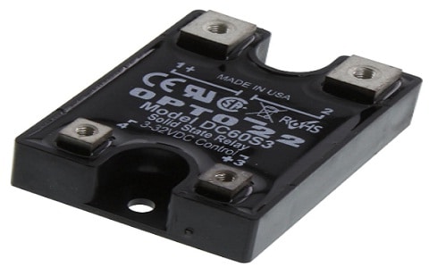
Solid State Relay or SSR
Solid State Relay Working Principle
The solid-state relay works on the semiconductor technology principle. The working of this relay follows as;
Whenever a low-voltage input control signal is provided to the input terminals of this relay then it turns on the control electronics. These control electronics utilize this input control signal for triggering the semiconductor switch like a thyristor (or) MOSFET within the output circuit. So this switch allows the flow of current from the input side to the output. Once the semiconductor switch activates, it will continuously conduct until the control signal eliminates it, thus permitting a high-voltage load to electronically connect and disconnect on the output side. In between the input & output circuits, the isolation barrier ensures no electrical connection directly. So this isolation will improve security and reduce the electrical noise risk.
Solid State Relay Block Diagram
A solid-state relay has four terminals, with two serving as input control terminals and the remaining two as output control terminals. These relays have numerous types and specifications. The block diagram of a solid state relay shows three parts: Input Circuit, Drive Circuit, and Output Circuit.

SSR Block Diagram
The input circuit in this block diagram connects to an IR LED that generates light whenever it couples to a power supply. The output circuit connects with power MOSFETs & Photodiodes where MOSFETs generally connect back-to-back in the reverse direction.
MOSFET in standard conditions does not conduct currents. So whenever the power supply is provided to the input of the solid state relay, then its IR LED generates lights that drop upon the photodiode. This photodiode produces voltage & current which switches on the Power MOSFET & the MOSFET starts conducting current.
Solid State Relay Circuit with BUZ71A
An SSR is designed mainly for switching an AC or DC load. The output of this relay mainly depends on the kind of switching device utilized in their circuits like a transistor, an SCR, or a TRIAC. Here a 12V DC SSR circuit is designed with a MOSFET & an optocoupler. So these relays do not have any moving parts but they work like mechanical relays they switch ON & OFF very fast as compared to mechanical relays.
The required components to make this 12V DC SSR circuit mainly include; a 5 to 12V DC supply, PC817 Optocoupler, BUZ71A MOSFET, 10K, and 470Ω resistors. Thus, connect this circuit as per the diagram shown below.
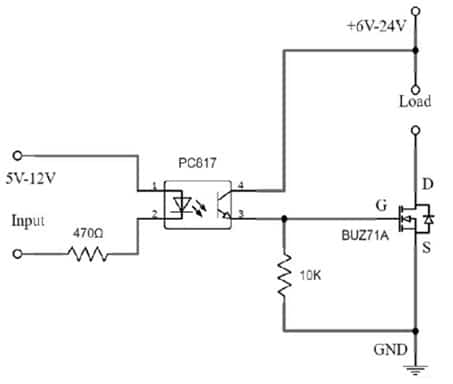
Solid State Relay Circuit with BUZ71A
Working
The solid-state relay circuit working is very simple to understand. The SSR circuit receives a 5V to 12V input signal and passes it to the PC817 optocoupler, which internally contains a phototransistor that enables and transmits the output. The output from the optocoupler serves as the input for the BUZ71A MOSFET, causing it to conduct and trigger the connected DC load across the transistor. This solid-state relay circuit easily handles a 10 Amp DC load. A high ampere-based MOSFET transistor is utilized to drive a higher DC load, such as the IRFZ44N MOSFET, which can drive a 40 Amp load.
This circuit can be used as an isolator to drive any motor for your Arduino or microcontroller projects. SSR circuit is used as a Latching circuit and it can be used when a high load switching is required.
Solid State Relay Types
Solid state relays are classified into four types based on their switching methods and applications which are discussed below.
Instant ON Solid State Relay
These types of solid-state relays switches on the load circuit immediately whenever an adequate input voltage is provided. When the input voltage is detached & the load current crosses the next zero volts then it turns off. So this SSR is mainly designed for controlling the inductive loads. These are applicable practically in the switching of starters, magnetic valves, contactors, and many more.
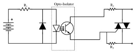
Instant ON Solid State Relay
Zero Switching SSRs
This type of SSR turns ON whenever an input voltage is provided & the load AC voltage crosses the next zero voltage. The relay turns OFF whenever the input voltage is detached and the AC voltage of the load achieves zero volts. A zero-crossing circuit achieves the operation of zero switching relay here. This circuit helps in detecting the zero cross of voltage & turns ON the TRIAC. These relays are designed mainly for controlling resistive loads. The applications of zero-switching SSR mainly include; soldering irons, heating elements temperature control, ovens, and many more.
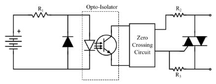
Zero Switching SSR
Peak Switching SSR
This relay activates whenever the o/p ac voltage achieves its next peak after providing the necessary control input voltage. The input control voltage turns off the output after it is removed and the output AC crosses its zero. A peak control circuit is used to detect the peak of the output AC voltage and fire the TRIAC whenever the output AC voltage strikes its peak. Peak switching SSR controls transformers of switching, high inductive loads, and large motors.
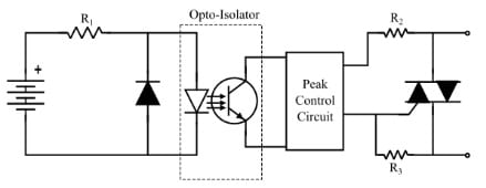
Peak Switching SSR
Analog Switching SSR
These relay switching mainly depend on the input voltage amplitude. The starting o/p voltage of these SSRs is proportional to the i/p control voltage. This type of solid-state relay turns off whenever the control input voltage is removed and the output AC crosses its zero volts. Thus, designers design solid-state relays with a synchronizing circuit that controls the output voltage quantity as a function of the input control voltage. So, manufacturers design these relays mainly for closed-loop applications such as temperature control.
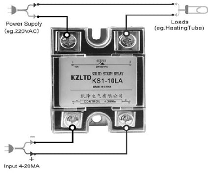
Analog Switching SSR
Static Relay Vs Electromagnetic Relay
The difference between static relay Vs electromagnetic relay includes the following.
Static Relay | Electromagnetic Relay |
| SSRs come in different kinds, each with unique features that various applications like heating systems, medical equipment, and industrial controls | An electromagnetic relay performs the function of switching by utilizing an electromagnet. |
| The short form of this relay is SSR, also known as solid state relay. | The short form of this relay is EMR, also known as electromechanical relay. |
| The components of this relay include a semiconductor switching device, optocoupler, and set of i/p & o/p terminals. | The components of this relay include an electromagnet, moving armature & set of i/p, and switching terminals. |
| This relay operates on the optical & electrical properties of semiconductors. | This relay works on the electromagnetic induction principle. |
| It doesn’t have any moving parts. | It doesn’t have any moving parts like armature. |
| Static relay does not generate switching noise. | Electro-magnetic relay generates switching noise. |
| This relay consumes extremely little power in mW. | Electromagnetic type relay consumes high power. |
| Static relay does not have any arcing problem at switching terminals. | This relay has an arcing problem at contact terminals within the electromagnetic relays. |
| It doesn’t need a substitute for contact terminals. | The contact terminal replacement is required. |
| This relay can be connected in any position & at any position. | Electromagnetic type relay is connected in a straight position always from the magnetic fields. |
| This relay performs several functions. | An electromagnetic relay performs a single function only. |
| This type of relay operation doesn’t affect the gravitation force. | This relay operation is affected by gravitation force. |
| This relay is not affected by shocks & vibrations | Electromagnetic relays are not affected by vibrations & shocks. |
| These relays can be damaged due to high temperatures. | This relay can be damaged because of temperature changes. |
| This relay size is compact. | These are large. |
| This relay accuracy is high. | These relays have low accuracy. |
| This type of relay is fast. | These relays are slow. |
| This relay is expensive. | This relay is not expensive. |
SSR Wiring Diagram
The Solid State Relay wiring diagram is shown below. This wiring diagram is very helpful in controlling an electric heater automatically. This wiring diagram uses an SSR, switchboard, heater, temperature sensor, and temperature meter.
The heater in this wiring is operating with a 230V AC supply. The temperature meter in normal conditions provides a 12V DC constant input signal to the solid state relay & it makes the heater turn ON. Whenever the generated heat by the heater goes beyond a certain limit the immediate temperature meter stops the input signal toward the relay. Thus this relay and also the Heater will get turned off. Here, the 12V DC power supply is utilized for controlling a 230V AC-based power supply system.
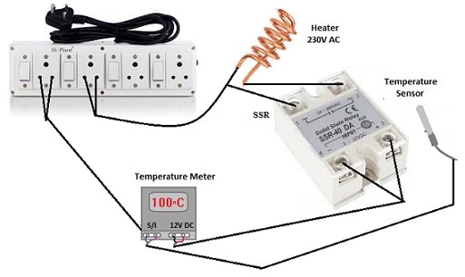
Solid State Relay Wiring Diagram
Advantages & Disadvantages
The advantages of solid state relay include the following.
- Its switching speed is high.
- These relays function well through pulse signals.
- This relay doesn’t have a latching problem.
- It gives extremely high efficiency.
- It works with extremely low current & voltage as compared to a typical electromagnetic relay.
- There is no sparking or ARC throughout the operation.
- This relay handles a large amount of current.
- This relay can turn on & off at zero (or) near voltage.
- Its size is compact.
- Its lifespan is long.
- It provides very quick response generally about 1µs ON & 0.5 µs OFF.
- These are very small in size and extremely durable.
- It provides less power consumption because of low current requirements like; 5mA @5VDC.
- It is not sensitive to vibration.
- This relay doesn’t have any coils within the design so that introduces back EMF into the circuit.
The disadvantages of solid-state relays include the following.
- These costs very high.
- This relay has specific voltage or current characteristics.
- There is a voltage drop occurs at the output because of internal impedance.
- It is low efficient and also negligible mainly for the operation of high voltage switching operation.
- This relay has a leakage current problem at the output even if it is in OFF mode.
- Solid state relay produces waste heat throughout ON mode.
- This kind of relay is activated by brief voltage spikes on the input side.
- The voltage transients can result sometimes in false switching.
- This relay provides non-linear voltage-current characteristics.
- It is susceptible to spikes & surges.
Applications
The applications of solid state relay include the following.
- Solid state relays use low DC voltage to control AC loads, providing simple AC load control.
- Different household circuits use these relays to switch AC loads.
- Heater control and power control applications use SSRs, as well as high-frequency applications.
- Additionally, they use SSRs with programmable devices like PLCs and microprocessors.
- The applications of these relays range from different applications which range from home automation applications to motor control in industrial areas.
- It is well suited in process applications wherever a PLC or any circuit based on microcontroller controls simply a machine tool.
- This relay helps control AC and DC motors in home appliances and industrial sectors.
- It switches loads like LED arrays and light bulbs.
- Heating systems for AC, furnaces, industrial heaters, and electric ovens use these broadly.
- Medical equipment uses SSRs to turn on and off the power.
- The automotive field uses these relays.
- This relay replaces older mechanical relays quickly in headlamp dimming circuits, fog lamp control & engine management system applications.
- These control water pumps by turning them on and off.
- CNC automation systems frequently use SSRs mainly for different reasons because these relays control loads precisely and quickly.
- Communication systems frequently use solid-state relay because they require reliable and fast high currents and voltage switching
Solid State Relay Problems & Solutions
Solid state relay provides many benefits like reliability, low noise, safety, sensitivity, no arc, etc. However, these relays face some problems due to their limitations within their physical structure and electrical performance such as over-heating, over-voltage, and over-current.
The main reasons for these problems are; poor cooling, not enough load capacity, very high input voltage, aging of SSR components, and short circuit or excessive load.
Overheating is generally caused by huge power loss within the internal relay components. So, while designing & utilizing these relays, you have to observe every part of heat distribution and take efficient heat dissipation measures like adding ventilation holes, heat sinks, and many more.
The load terminal voltage or input of the relay can cause overvoltage above the rated value. When choosing this relay, you must select the suitable voltage rating depending on the needs of the circuit. Additionally, add a varistor for overvoltage protection before the relay.
The load current beyond the relay’s rated current can cause overcurrent. To keep away from overcurrent while choosing this relay, choose the value of rated current depending on the demand of actual current of connected load, or add a fuse or current limiting resistor ahead of the relay for overcurrent safety.
What is a static overcurrent relay?
A static overcurrent relay is a protection device that recognizes abnormal levels of current within power systems. This relay also operates depending on measuring current magnitudes & compares them with pre-set thresholds.
Which is a static relay?
A static relay in electrical systems is a kind of electrically operated switch where that doesn’t have moving parts.
What are the basic elements of static relay?
The basic static relay elements are; the input element, output element, feed element, and measuring element.
Thus, this is an overview of solid state relay, block diagram, circuit, working, types, advantages, disadvantages, and applications. Solid State Relays are critical components within modern electrical systems. So these components have changed the world of electrical control systems with their speed, reliability & durability. Thus, these relays play a significant role in different industries by providing safe and very efficient operation to multiple devices & systems. SSRs come in different kinds, each with unique features that various applications like heating systems, medical equipment, and industrial controls. Here is a question for you, what is a relay?