The flow in industrial processing is the movement of gases, liquids, and steam throughout a processing system. So, the measurement of flow rate is mainly used for measuring the amount of fluid process media supplied throughout a particular cross-sectional region for each unit of time. In an industrial system, flow rate measurement monitoring is significant to control the secure fluid’s movement. This switch is used to monitor & control the flow within all industries to process fluid media like; liquids, gases & steam. Similar to all types of switches, a flow switch is a device used to make & break the flow of current within a circuit. This article provides an overview of a flow switch, its working, and its applications.
What is Flow Switch?
A flow switch is a device that helps maintain secure and manageable flow rates by activating necessary actions within different machines of an industry to provide flow control for process media like; liquid, steam, or gas. These switches are simple and separate units that monitor the flow rates & triggers at a particular flow rate. Whenever the flow achieves a certain fixed flow rate, then a switch is activated that can shut down the flow completely and it can be done through electrical signals formed by the switching mechanism. These switches handle a wide range of different media, but certainly, the most common media for these switches are air & water.
Symbol
The flow switch symbols are shown below. These switches can be configured as either Normally Open or Normally Closed and it refers to the default condition of the switch. With a normally open switch, the circuit will be opened (OFF) whereas with a normally closed switch, the circuit will be closed (ON).
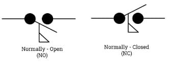
Flow Switch Symbols
Construction
The construction of the flow switch is shown below which is designed with a paddle system, reed contact, permanent magnet, and a second magnet which are discussed below.
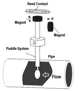
Construction
In the pipeline, the fluid flow simply pushes the switch paddle to move within the direction of fluid flow. To activate the paddle, the necessary fluid flow depends mainly on the line size.
A permanent magnet is attached at the pinnacle of the paddle which is used to operate a reed switch to give a potential-free output.
A reed contact in this switch is connected at the outside of the fluid flow on the magnet.
A second magnet of this switch has a reverse polarity that is mainly used for generating a reset force.
Whenever the paddle system approaches contact through the fluid flow which needs to be monitored then it moves. The permanent magnet changes its place in the reed switch contact. This reed switch contact will be turned ON/OFF depending on the contact type. Once the flow of liquid is interrupted, the paddle within the switch will come back to its actual place. So this change in the contact is used mainly to specify the necessary output flow signal. These switches are very helpful in protecting a pipe whenever the flow of fluid through a particular line needs to be monitored.
Working Principle
The working principle of the flow switch is based on a free-floating magnetic piston that only reacts to the fluid’s motion within the pipeline and not to static (or) system pressures. In the presence of water flow within a pipe, the piston’s controlled movement activates a reed switch which is hermetically sealed externally. This switch is simply used for activating audible (or) visual alarms & relays (or) other controls.
These switches help in determining if the rate of flow is below or above a fixed flow rate, then the set point is adjustable or fixed. Whenever the set point is achieved, then the response drives an electric circuit. Whenever the switch is activated, then it will stay in that state until the flow rate goes back from the fixed point through some amount.
Specifications
The most significant operating & performance considerations mainly include the following.
- The type of media is significant to consider while choosing a switch.
- The diameter of the pipe describes the pipe size within the system. This switch must fit strongly above the pipe, thus it is significant to identify the diameter of the pipe while choosing this switch.
- The operating pressure is the highest head force of the process media that the device can resist. So this factor must be considered whenever choosing the switch material.
- The highest media temperature range that can be monitored is generally dependent on liner materials & construction.
Flow Switch Connection Diagram
The flow switch connection diagram is shown below which is used to manage the fluid supply within the pipe. This switch is arranged in a pipe that includes electrical contacts that are both typically normally open & normally closed. This switch either opens (or) closes to generate a sound alarm (or) light signal whenever there is no flow with the normally closed contacts of the switch.
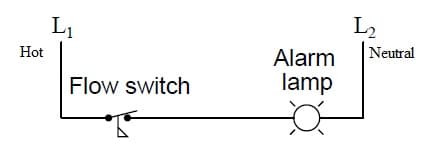
Flow Switch Connection Diagram
In the above circuit, the switch is physically mounted. So this particular switch is used for triggering an alarm light when coolant flow throughout the pipe ever drops to a severely low level & the switch normally-closed contacts are indicated by the closed status within the circuit. Even though this switch is normally designated as “normally closed,” it will spend most of its life span being held within the open condition by the occurrence of sufficient coolant flow throughout the pipe.
Whenever the rate of fluid flow hits the contacts of the switch then either the circuit can be opened or closed by generating an alert. The switch in the circuit can be arranged as either NC (Normally Closed) or NO (Normally Open). This circuit is off whenever the switch is within the NO position and if the switch is in the NC position, then the circuit is ON. Whenever the fluid flow throughout the pipe slows down enough then this switch will return to its “normal” status & conduct power supply to the alarm lamp.
Flow Switch Types
These switches are available in different types which are discussed below.
Diaphragm Flow Switch
Diaphragm type switch is the same as a differential pressure switch but the main variation between these two is there is a gap that allows the flow of fluid throughout the change between the two inlets and the outlet ports. In this switch body, the fluid flow normally takes a zigzag route when this is completed. Thus this effect will result in a significant pressure drop, which happens whenever a fluid flows through the switch.
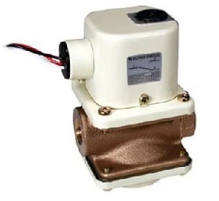
Diaphragm Type
Paddle Flow Switches
The paddle type is also known as a flapper-type flow switch because it has a flapper or paddle device. This switch is designed with a spring-mounted or hinged paddle to build direct touch through the media supplied throughout the pipe. This switch has some features like; strong construction, high performance, compact design, & has longer functional life.
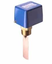
Paddle Flow Switch
The paddle is connected through the flat surface & the fluid direction flow can be faced through a hinge. In this switch, a permanent magnet is connected to this end & a reed contact is connected on top of this magnet at the external side of the fluid flow. These types of switches are used in different chemical industries to monitor the flow of liquid in the pipelines.
Solid-State Flow Switch
Sold state type is also known as or thermal flow switch which operates on the heat transfer principle. This type of switch has two temperature sensors where one temperature sensor is used for measuring the temperature of media wherever this switch is submerged & the second temperature sensor is connected very close to a permanent heating element.
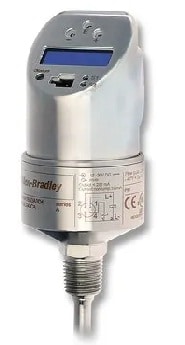
Solid State Type
Whenever the fluid flow rate is enhanced then it has the cooling effect of the heated sensor. Thus the fluid’s flow rate is higher, cooling will be more. So the reduction of temperature between the two temperature sensors indicates that the fluid flow rate goes beyond the modifiable set point. When the fluid flow rate reduces then cooling will be low which causes an increase in the temperature difference.
Shuttle Flow Switch
A shuttle flow switch or piston switch simply responds to the rate of fluid flow within a pipe. The piston movement in this switch activates a reed switch which is sealed hermetically and it causes the necessary action to be taken whenever the fluid flow rate improves or reduces. This type of switch operates because of the velocity (or) differential force of the fluid on a disk based on the moving force concept.
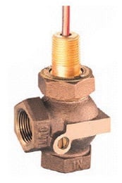
Shuttle Type
A shuttle in this switch is connected at the bottom & a magnet is connected to the disk. The higher part of the shuttle body will work against a gravitational power. Once the liquid flow increases to the actuation region then the shuttle will be displaced. This shuttle will control the reed switch within the unit stem when displaced throughout the fluid flow and the shuttle will come back whenever the fluid flow decreases.
Other Flow Switches
Flow switches are classified based on the flowing media used which are discussed below.
Gas Flow Switches
The media used in these switches are air & steam. These are normally used within HVAC applications for detecting gas velocity. One of the crucial parameters of these switches is the flow rate of fluid will be measured. In this switch, a rotating device measures how much fluid goes supplied throughout the switch. Whenever the flow of fluid achieves a specific pace, the vane triggers a set of switch contacts that complete a circuit. By using these switches, air flow & vapors can also be measured.
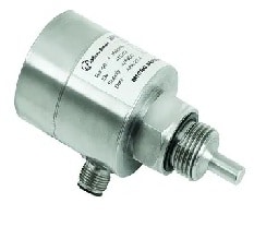
Gas Flow Switch
Liquid Flow Switches
These switches use media like; chemicals, slurries, water & lubricants. These types of switches are used in a broad range of industrial applications to measure slurries, lubricants, water & chemicals. These switches are used mostly in automated industrial systems to process liquid media to promise secure and best fluid flow rates.
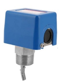
Liquid Flow Switch
Volumetric Flow Switches
Volumetric type switches are used to measure the flow of liquids or gases and this measurement can be done depending on volume for each unit of time. These switches are used mostly to measure the gas (or) liquid flow. The volume for every unit of time can decide how this measurement is performed.
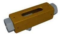
Volumetric Type
Velocity Flow Switches
Velocity-type switches are devices that work linearly concerning volume flow rate. These switches are mainly used for measuring the moving fluid’s flow rate in terms of velocity or feet for each minute. These types of switches are normally used to measure the rate at which point fluid flows. So, this measurement is made in terms of feet for each minute or speed. For these types of switches, the typical analog electrical o/p are; voltage, current, frequency (or) switched output.
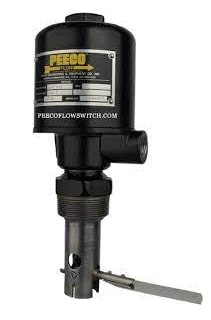
Velocity Flow Switch
How Do You Test a Flow Switch?
Testing a flow switch is crucial to ensure that the readings of this switch are accurate & the mechanism utilized is in perfect condition. These switches are usually tested every three months. These tests are valid only whenever sufficient water supplies throughout the switch. The fluid pressure in the two sides of the switch must be equivalent before the test.
At the switch testing, water is supplied in the switch downstream then it leads to a pressure drop & the switch will swing. So the switch must be tested whenever there is a small disturbance to work, thus engineers frequently test these switches before anybody goes to work.
The steps involved in testing a flow switch are;
- Place the cover on top of the switch & turn on the power.
- Start fluid flow throughout the designated system.
- Monitor fluid flow in operation to decide if the switch is properly working.
- This process needs to be repeated several times to make sure the switch as well as the designated system is working correctly or not.
- If this switch is working not properly, then adjustments need to be made. This switch must be changed every five years.
Advantages & Disadvantages
The advantages of flow switch include the following.
- These switches are very reliable devices.
- These switches provide adaptability, affordability & precision.
- These switches optimize process control, ensuring that the correct amount of water is supplied throughout the system at all times. So this helps in reducing energy consumption & enhance the overall efficiency.
- These switches detect anomalous flow rates (or) blockages within the system to assist in preventing equipment damage or accidents.
- These switches are used for triggering alarms (or) shut off systems while happening a problem and help in maintaining control above the process & reducing disruptions.
- By enhancing efficiency & decreasing the risk of disasters (or) equipment breaks, these switches help save money on repairs & energy costs.
- By monitoring the fluid velocity and flow rate continuously, these switches help ensure that the system is working at peak performance or not and also improve reliability & uptime.
The disadvantages of flow switches include the following.
- Gas inclusions in the fluid pipe cause errors.
- These switches provide reduced conductivity.
- It needs maintenance.
- These are costly to install.
- It is vulnerable to corrosion caused by fluids with a water base.
- These switches have intricate design.
- It has poor stability.
- Low-density liquids are not possible to measure.
- It needs clean fluid.
- If the flow rate of liquid rises, then the switch size needs to increase.
- It cannot measure fluids with less density.
- These are very sensitive to vibration interference.
Applications
The applications of flow switches include the following.
- These switches are used to detect the fluid flow rate within the pipes.
- These switches can also be used to detect if a ventilation fan within a hazardous area fails & airflow has been blocked.
- This switch helps protect the electric heating element of the central heating system from being strengthened before the flow of air from the blower is found.
- These are used to monitor drain line flow, safety spray nozzle, testing oil well system, protection of pump & monitoring of relief valve.
- These switches are mainly used for monitoring fluid flow rate & an industrial process system control.
- These switches are used within pump staging, failure of pump or valve, protection of flow & detection of flow (or) blockage.
- These switches are normally used in reservoirs as well as tank storage systems for maintaining the water tanks at the preferred level.
- Large-type switches are used for HVAC systems within big and commercial buildings.
- These switches are used commonly in pipelines to make sure that the media flow throughout the pipeline is continuous.
What is a Flow Switch used for?
These switches are mainly used for monitoring & controlling the flow rate of fluid in an industrial process system because automated industrial systems heavily rely on switches to ensure secure & best flow rates.
Where do you put a Flow Switch?
This switch must be placed in a horizontal or vertical suction of pipe based on the fluid flow.
What is the Difference between Pressure Switch and Flow Switch?
The main difference between a pressure switch and a flow switch is that the pressure switch easily reacts to changes within fluid pressure whereas a flow switch reacts to changes within the flow rate of fluid. In addition, pressure switches mainly serve security functions by shutting down the system when pressure-related problems occur whereas flow switches activate and deactivate the pressure washer system depending on the flow of water.
What is the Difference between Sensor and Switch?
A sensor is an electronic device that detects & reacts to some kind of input from the physical surroundings like heat, light, motion, pressure, moisture, etc. A switch is an electrical device that reacts to an outside force to change an electric signal mechanically.
Is a Flow Switch Normally Open or Closed?
This switch is either configured to be NO (Normally Open) or NC (Normally Closed) and it refers to the default condition of the switch.
What is the Flow Switch in the Boiler?
This switch in a boiler is used to prevent the boiler from igniting if there is very much gas within the system.
Thus, this is an overview of a flow switch, construction, working, circuit, types, advantages, disadvantages, and applications. This switch is used to check the flow rate & pressure of fluids, gaseous media throughout a duct or a loop. These switches can be used for monitoring the flow over a specified period to monitor the whole fluid flow continuously. Here is a question for you; what is a flow sensor?