First of all, knowing what is LVDT, its definition must be elaborated. LVDT is defined as a sensor which converts a nonlinear motion to an electrical signal. There are different LVDT types such as displacement etc. The linear variable differential transformers have no requirements of electrical contact amid its moving parts either core rod assembly or probe etc. and transformer itself, however, it has reliance over electromagnetic coupling.
This is the main reason why these transformers operate without having built-in circuitry and due to this, these transformers are utilized widely in the areas where there is a requirement for higher reliability and long life. There are a variety of LVDT applications. These transformers are also capable to work under extreme conditions and LVDT applications comprise of aerospace and military use.

LVDT Construction
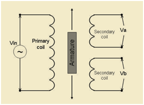
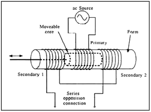
The primary coil of linear variable differential transformers winding is wound on the entire length of non-ferromagnetic liner or bobbin which is typically made of some ceramic or plastic material. There are a total of two secondary coils which are always wounded on the top of the primary coil. Both secondary coils are connected in opposite directions but in series. The following is the circuit diagram or LVDT diagram also known as a block diagram.

A ferromagnetic core is attached to the metal or object which is needed to be measured sliding along the axis of the tube and is also coupling it magnetically to that of primary and secondary windings which are adjusted at the length of the core. The secondary windings of long stroke linear variable differential transformer having both windings to be wounded at the exact same time through the use of custom design and computerized winding machines. This technique saves time in manufacturing as well as it also creates the secondary windings with that of distribution of symmetrical capacitance, hence allowing to meet required specification with ease.
LVDT Working Principle
These paragraphs are dealing with LVDT working or LVDT principle of operation. By the time when primary coil of the transformer is excited having a sine wave voltage (Vin) excitation, it is generating an adaptable magnetic field which is always concentrated through the core and is induced by the sine wave of the secondary coil. The secondary windings of the transformers are designed so as to have the differential voltage (Va-Vb) exactly to be proportional to the core position from that of the null position.
Therefore the (Va-Vb) phase shift as with the reference of excitation which is close to a Zero degree or either close to 180 degrees purely depending upon direction is determining its direction from that of the zero position of mechanical aspect. The null position is actually zero position and is mentioned as the position of the core where the phase angle of the difference in voltages (Va-Vb) is equal to 90 degrees.

The difference in voltages among the two secondary windings (Va-Vb) whenever the core is at a position of mechanical zero which is also known as the null position is known as the null voltage and the phase angle at the null voltage is equal to 90 degrees. The null voltage is also known as the quadrature voltage. The residual voltage is because of the complex nature of the electrical model of a linear variable differential transformer which comprises of parasitic capacitances of the windings. The complex nature of the transformer is also having a phase angle of either 0 or 180 degrees whenever the core is far away from the null position.
The Effect of Temperature on LVDT
The coefficient of temperature which is also known as sensitivity calculated as the output per unit of displacement is premeditated through the help of a number of windings along with the geometry of the armature as well as permeability and resistivity of the metals which are used in the construction of LVDT. The shift in the null position is purely affected through the coefficient of expansions as well as the length of the materials which are used in the LVDT transducer construction. Therefore, this is a highly repeatable and predictable reference position.
Applications of LVDT
The linear variable differential transformer is used in a variety of applications. Such transformers can be used as the position sensor with absolute accuracy. This is why these are known as the LVDT sensor. The LVDT datasheets are readily available online. In cases when there is no power, LVDTs are capable to show the measurements when switched ON. This shows that in such transformers none of the positional information is being utilized. The LVDTs are most commonly utilized in the positive feedback of servomechanisms and also for the automated measurements in the tools of machines along with other scientific and industrial applications.
Theory of LVDT
As stated earlier, LVDTs are having two secondary coils and a single primary coil. The secondary coils are moveable over the magnetic core while both primary and secondary coils are joined together in a barrel having mobile magnetic core rod which is always inside of the barrel.
LVDT characteristic also includes its employment for computing deflection of CB. The following is a detailed procedure.
- First of all, measuring the dimensions and are of a cross-section of the beam. After the calculation of the area, a moment of inertia is needed to be calculated. This is also known as LVDT calibration.
- Moving the mounting block of LVDT over the beam and then over its support hand over the base of its assigned position.
- The third step is to tighten the screws and then record the position of LVDT with respect to that of the fixed end of the beam.
- Moving the weight disk to the assigned position over the beam and then recording its distance from that of a center to the end of the fixed beam.
- Next step is to turn on the power to the LVDT and then record various digital readouts from the indicator of TIC-9000. The indicator is capable to display values from -0.200 till +0.200 in inches.
- After then applying a weight which is known and moving it on to the disk located near the beam.
- Recording values from the indicator.
