In any electrical system, the highest amount of power is used to transmit the power to the load for its operation. the best example of this is an audio amplifier as they transmit the maximum amount of current from the amplifier to the speaker. Similarly, in radio system, the highest amount of current is supplied from the power amplifier to the antenna. For this, the value of load resistance should be ideal for supplying the highest amount of current toward the load. Therefore, the value of load resistance should be of ideal value. If it is either less than or greater than the ideal value the maximum amount of power will not be transmitted. So, to maintain the ideal value of load resistance we developed a theorem I,e maximum power transfer theorem. It assists in detecting the maximum power transmitted to the load. In this article, we will study what is Maximum Power Theorem? Definition, steps to solve different circuits, solving some examples, and applications.
Maximum Power Transfer Theorem (MPT) Definition
In a linear bilateral network, across the load circuit, if the network is replaced by a single voltage source with series impedance (Thevenin’s theorem), then the maximum power is transferred from the source to the load circuit. The load impedance is the complex conjugate of the source impedance.
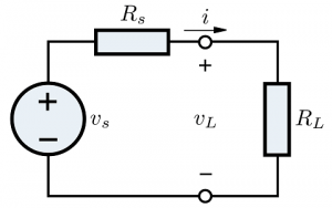
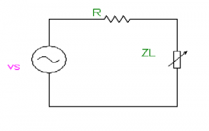
Maximum Power Transfer circuit
Zs = Rs + JXs , Zl = RL+ JXl
Where
Rs = source resistance,
Xs = source reactance,
Rl = Load resistance,
Xl = Load reactance.
Thevenin’s Resistance
In the given circuit, Thevenin’s resistance is observed by switching off all the independent sources available considering only the resistance.
Thevenin’s Theorem
In any circuit, Thevenin’s equivalent is represented as the voltage source in series with the Thevenin’s resistance.
For maximum power transfer theorem,
Zl = Zs*
(RL + JXl) = (Rs + JXs)*
(RL + JXl) = Rs – JXs
RL= Rs ; Xl = Xs
Properties or Applications of Maximum Power Transfer Theorem
- This theorem is applicable for linear networks I.e the networks with R, L, C, and linear controlled sources as elements.
- The presence of dependent sources makes the network active and hence, this theorem is used for both active as well as passive networks.
- Maximum power transfer theorem is applicable only when the load is variable. Otherwise, choose the minimum internal impedance of the source which results in maximum current through the fixed load. Hence, maximum power is dissipated by the load circuit.
Steps to Solve Maximum Transfer Power Theorem
DC Source with Variable Resistor
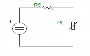

DC Source with Variable Resistor
PRl = (IRl)2 RL
(Vs/ Rs + RL)2 RL ,
For MPT ( Maximum power transfer theorem)
Dp/dRL= 0
d/dRl (sV2. Rl/(Rl+Rl)2) = 0
(Rs + Rl)2 = 2.Rl (Rs + Rl )
Rs + Rl = 2.Rl
Rl = Rs
Therefore, Pmax = sV2. Rl/(2.Rl)2
Pmax = (Vs)2. Rl/(4.(Rl)2
Pmax = (Vs)2/4.Rl Watts
AC Source with Variable Load Impedance
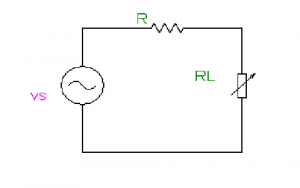
Load Resistor which is only Variable.
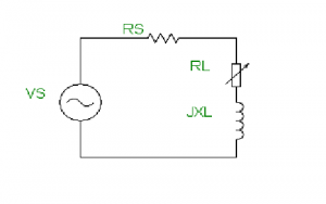
AC Source with Variable Load Resistor
I = Vs /Zs + Zl
Pl = (Is)2 . RL
For MPT dPl/dRL = 0
RL= √(Rs)2 + ( Xl + Xs )2
Imax at RL = √(Rs)2 + ( Xl + Xs )2 = Vs /Zs + Zl Amperes
Pmax = (Imax)2.RL Watts
Load Reactance which is only Variable
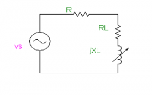
AC Source with Variable Load Reactance
I = Vs /Zs + Zl
Pl = (Is)2 . RL
For MPT dPl/dXl = 0
Xl = Xs
Imax at ( Xl = Xs )= Vs /Zs + Zl Amperes
Pmax = (Imax)2.RLWatts
Load Impedance is Variable
AC Source with Variable Load Impedance
I = Vs /Zs + Zl
Pl = (Is)2 . RL
For MPT dPl/dZl = 0
Zl = Zs*
Pmax = = (Vs)2/4.RL Watts
AC Source with only Variable ‘R’ as Load
AC Source with Only Variable Load Resistor
I = Vs /Zs + Zl
Pl = (Is)2 . Rl
For MPT dPl/dRl = 0
Rl = √(Rs)2 + ( Xs )2
Imax at Rl = √(Rs)2 + ( Xs )2 = Vs /(Zs + Zl )Amperes
Pmax = (Imax)2.(R)l Watts
Maximum Power Transfer Theorem problems with Solutions
Find Rl for MPT to Load?
Similar to Case 3
I = Vs /Zs + Zl
Zs = Rs + JXs = 2 + j. 2πfl;
Xl = 2πfl = 2π(1/π).1 = 2Ω
Find RL Value for MPT?
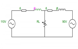
Find RL by MPTT
Convert the given circuit into Thevenin’s equivalent circuit

Equivalent Resistance
For Rth short circuit voltage source
(6 +j8) parallel to ( 6 + j8)
Zth = Rth + jXth = ( 3 + j4 ) Ω
Rl = √(Rs)2 + ( Xs )2 = √32 + 42 = 5Ω
Find the Power in RL

Power in Rl
From Sub Case 2
For MPT, Xl = Xs
Xc = 10 Ω
Pmax = = (Vs)2/4.Rl Watts = 1002 / 4*10 =250 W
Please refer to this link for Maximum Power Transfer Theorem MCQs.
Applications of MPTT
The application of MPTT is such that, where all the independent voltage sources are switched off and the equivalent impedance is only considered. Then only, the maximum amount of power is transmitted. The practical applications of MPTT are explained below
- MPTT is applied in Radio communications, where the power amplifier transmits the maximum amount of signal to the antenna if and only if load impedance in the circuit is equal to the source impedance.
- It is also applied in audio systems, where the voice is to be transmitted to the speaker. The amplifier amplifies the maximum amount of voice when the load impedance is equal to the source impedance.
Know more about Norton’s Theorem MCQs.
Thus, in this article, we studied how the maximum amount of power is transmitted to the load I,e when the value of load resistance is equal to the Thevenin’s resistance. Apart from this, we also studied the definition, steps to solve different circuits, examples of solving them and applications of MPT. Here is a question for the students, please find RL using the following circuit.