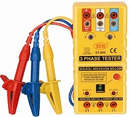
Phase Sequence Meter
Phase sequence meter is used for detecting the sequence of the supply in three-phase electric circuits. Since the direction of rotation of three phase electric motors can be changed by changing the phase sequence of supply. And also the correct operation of measuring instruments like 3 phase energy meter and automatic control of devices also depend on the phase sequence. Different types of phase sequence testers are available in today’s market like contact or non contact, static or rotating, etc., in a wide range of voltage or power ratings.
What is Phase Sequence?
The sequence in which three phase voltages attain their positive maximum values is defined as the phase sequence. It refers to the relation between the voltages or currents in three phase system. Consider the three phases as red-R, yellow-Y and blue-B phases.
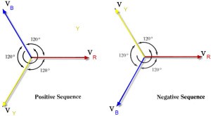
Phase sequence in Three Phase System
The phase sequence can be taken as RYB if R attains its maximum value first with respect to the reference in anti-clockwise direction followed by Y phase 120° later, and B phase 240° later than the R phase.
The phase sequence can be taken as RBY if R followed by B phase is at 120° later and Y phase is at 240° later than the R phase. RYB is considered as a positive sequence, whereas RBY is a negative sequence supply, as shown in the figure.
What is a Phase Sequence Meter or Indicator and Its Working Principle?
The phase sequence meter is used for the detection of phase sequence in three phase circuits and there are different types of phase sequence indicators that are as follows:
Types of Phase Sequence Indicators
Phase sequence indicators can be classified into two types:
(a) Rotating Type
(b) Static Type
Rotating Type Phase Sequence Indicators
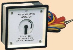
Rotating Type Phase Sequence Indicators
It works on the principle of induction motors. The principle of rotating type phase sequence indicator is similar to that of a three phase motor. Consider the working of a motor for a better understanding of these indicators. For three phase motors, we require three phase power supply, whereas this three phase power must be supplied in a particular sequence. Let us assume that the three phase supply given to the motor has a phase sequence of RYB, then the motor will rotate in clockwise direction – and, if the phase sequence of supply is reversed, then the motor will rotate in counter clockwise direction. This may cause severe problems to the load and entire system.
When a three phase supply is given to the coils, then the coils will produce a rotating magnetic field, and this rotating magnetic field produces eddy EMF in the rotatable aluminum disc, as shown in the diagram.
This eddy EMF produces eddy current on the aluminum disc, due to the interaction of the eddy currents with the rotating magnetic field a torque is produced which causes the aluminum disc to rotate. The clockwise direction rotation of the disc indicates the sequence as RYB, and the anti-clockwise rotation of the disc indicates the change in phase sequence.
Static Type Phase Sequence Indicator
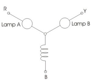
Static Type Phase Sequence Indicator with inductor
If the phase sequence is RYB, then the lamp B will glow brighter than the lamp A, and – if phase sequence is reversed – then the lamp A will glow brighter than the lamp B, as shown below in the lamp arrangement circuit diagram.
Now, let us see how this happens
Assume that the phase sequence is RYB, and consider the voltages as Vry, Vyb, Vbr as according to the diagram, and we have
Vry=V
Vyb=V(-0.5-j0.866)
Vbr=V(-0.5+j0.866)
Here, assuming a balanced operation such that we have Vry=Vbr=Vyb=V. We know that the algebraic sum of all phase currents is equal, then we can get the below equation.
Ir+Iy+Ib=0
From the above equations, we get the ratio of Ir and Iy as 0.27.
 It indicates that the voltage at the lamp A is only 27 percent of the lamp B. So, from this, we can observe that the lamp B will glow brighter than the lamp A in case of an RYB phase sequence. While in case of a reversed phase sequence, the lamp A is brighter than the lamp B.
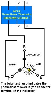
Similarly, from the above circuit by replacing the inductor with a capacitor, as shown in the below figure, the indicator works similar to the above phase indicator.
Here two resistors are connected in series with the two Neon lamps to protect the lamps from over current and breakdown voltages. If the three phase supply is in the sequence of RYB, then the lamp A will be ON, and the lamp B will be off, and if the supply sequence is reversed, then the lamp A will be off while the lamp B will be on.
Phase Sequence Checker
For a better understanding of this project, here we have designed a phase sequence checker project to detect the phases of three phase supply. As we know that, if the three supply phase sequence is changed or reversed then the loads like the three phase motors will operate in reverse direction which may lead to permanent fault.
So, in order to detect the phase sequence, the three phase sequence checker is used which consists of NAND and OR gates. If the sequence is proper, then the LEDs will run clockwise as they do not receive triggering signal from the gates.
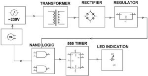
Block Diagram of Phase Sequence Checker
In this project, NAND and OR gates are placed in such a way that they produce a logic signal which is further given to the microcontroller. If the sequence is changed, then the gates generate the input signal to the microcontroller through a timer to drive the LEDs such that these indicate the change in phase sequence by running clockwise for sometime and anticlockwise for sometime after receiving the triggering signal. In this case, we can maintain continuous supply to critical load by using auto selection of any phase available in three phase supply system.
This is about the phase sequence meter types and working with a practical implemented circuit. You can know more about the given project by clicking the link attached to it. And write to us for more information about the circuit and for any technical help in the comments section below.
Photo Credits:
- Phase sequence meter by sew
- phase sequence by mechprod
- Static Type Phase Sequence Indicator with inductor by electrical4u
- Static type phase sequence meter with capacitor by webring