The first earth tester was invented in the year 1950 by Evershed and Vignoles Meggers who made the initial insulation as well as earth resistance testers. Analog grounding tester like М416 is the most frequently used in the USSR. Many organizations from the 21st century manufacture digital earth resistance meters as well as testers. The main function of this instrument is to decide the capability of the grounding for an electrical system. By a NEC (National Electrical Code) standard, the earth resistance must be below 25 Ohms to ground the installation consistently & efficiently. This article provides brief information on an earth tester, their work, and their applications.
What is an Earth Tester?
An earth tester is a soil resistance measuring instrument or grounding resistance tester that is used to measure the resistance of the earth. This instrument generates an electrical current and after that, it supplies to the measuring electrodes. So the potential difference between these two electrodes provides information regarding the soil resistance value.
The earth electrode is used in the power system to connect all the equipment to the earth. So the earth protects the equipment & workers from the fault current. The earth’s resistance is extremely low. The fault current throughout the earth electrode supplies toward the earth, so the system can be protected from damage.
The equipment of the earth electrode controls the high potential which can be caused by voltage spikes & high lightning surges. Before giving earthing to the equipment, it is necessary to decide the resistance of that specific region from where the earthen pit is dug. The earth must have low resistance so that the fault current supplies easily to the earth. The earth resistance can be decided through an earth tester instrument.
Earth Tester Construction
The earth tester construction is similar to the Megger with some modifications. This tester includes a rotating current reverser, a DC generator, a PMMC instrument & rectifier for measuring resistance. The earth tester circuit diagram to measure the earth’s soil resistance is given below.
A D.C generator in earth tester design is used for generating DC voltage for supplying the Earth merger because, for the Earth merger, this generator can be used as a source. This DC generator provides the voltage to the rotary current reverser.
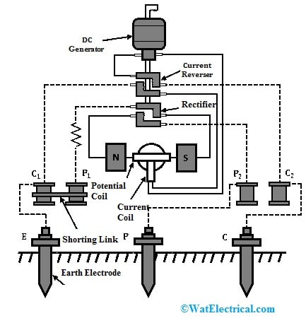
Earth Tester Construction
In this design, a current reverser helps in converting AC to AC so that the earth resistance test can be done through AC. This AC supply is provided to the earth electrode from the current reverser that is under test. Here the AC supply usage for earth resistance measuring is, the undesirable effects because of back e.m.f generated within the soil are removed.
The rectifier in this design is used because the earth tester is equipped with a moving coil instrument for measuring resistance. So the instrument’s current coil & pressure need a DC supply. This rectifier simply changes AC coming from the electrode to DC & supplied toward the current coil.
The potential coil/ pressure is coupled across the DC generator to measure the applied voltage. The current coil can be connected in series through the generator to measure the current supply throughout the electrode. Here both rectifier and current reverser are connected simply using two commutators which are located on the shaft of the DC generator. The set of fixed brushes is provided through each commutator for transmitting power from the rotary shaft to the fixed parts.
In the PMMC instrument, the term “PMMC” stands for permanent magnet moving coil which is used to measure the resistance of the earth within an earth tester. This instrument includes two pressure coils & two current coils where every current & pressure coils have two terminals. The single current coil & pressure coil pair can be located across the PMMC instrument whereas the other pair of these coils can be short-circuited & coupled to the auxiliary earth electrodes.
The current coil’s one end is connected to the DC generator whereas the other end is coupled to the earth electrode. Similarly, one end of the pressure coil is coupled to the DC rectifier whereas the other end is connected simply to the earth electrode. Here, the potential or pressure coil is arranged in between the permanent magnets & is connected simply to the pointer. This pointer is coupled to a calibrated fixed dial which indicates the earth resistance measured value on the dial.
Earth Tester Working
The earth tester includes four terminals where two are potential terminals which are indicated with P1, and P2, and current terminals which are indicated with C1, and C2.
The earth electrode ‘E’ is connected to the C1 & P1 terminals by simply shortening them whereas the two auxiliary electrodes P & C are connected simply to the P2 & C2 terminals correspondingly. The PMMC instrument’s potential & current coils are connected so that the voltage drop in between E & P electrodes can be applied across the potential coil & current throughout the current coil mainly depends on the earth resistance.
Whenever the DC generator is driven at its rated speed, the moving coil instrument’s pointer will deflect & the earth tester specifies the earth resistance. The pointer’s deflection can be specified by the voltage ratio across the potential coil as well as the current of the current coil.
Electrodes Positioning
Electrodes positioning is very significant while measuring the earth resistance because the wrong electrode position can reduce the amount of accuracy & invalidate measurements taken. To get the maximum amount of accuracy, the E earth electrode & C current electrode are located at a certain distance because two electrode resistance areas within the ground should not overlap with each other.
If there is a large difference within the values of resistance with the P electrode at various positions then the distance in between the two electrodes E & C should be enhanced. Until the measured values stay closely constant by the P electrode at various positions in between E & C then the relocation of E & C is done.
Types of Earth Tester
Earth tester types based on different methods for conducting earth ground testing are;
Stakeless Testing
This kind of earth test uses two clamps only where one clamp is used as a signal generator & other one is used as a receiver. It eliminates the requirement of temporary ground stakes & is very helpful when stakes cannot be driven into the earth. It can also eliminate very dangerous & time-consuming procedures for separating parallel grounds & finding a secure place for driving the stakes. This stateless technique is preferred mostly whenever parallel grounds are available & momentary ground stakes would be hard to drive within the ground. This technique can be done with the 1630-2 Earth Ground Clamp tool.
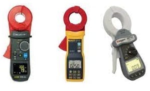
Stakeless Testing
Selective Earth Ground Testing
This technique uses a single clamp & two stakes which permits you to determine the resistance of the earth at specific installation parts, separating the system to verify what is in place. This testing method uses a current clamp when the electrode of interest is still under test. A Fluke 1625-2 clamp meter is used to separate the injected test current into the electrode under test.
In the soil, two earth stakes are located in a direct line which is away from the electrode of interest; generally, 20 meters of spacing is enough. The clamp meter is simply connected to the electrode & the Earth Ground Clamp meter can be arranged around the electrode to remove the parallel resistance effects within a ground system. So this allows the earth electrode of interest only to be measured.
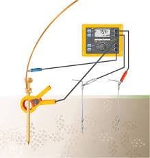
Selective Earth Ground Testing
Soil Resistivity Earth Ground Test
This technique uses four stakes which is utilized before earthing arrangement installation. The resistance measurements can be impacted by soil composition, temperature & moisture content, thus this testing is required to decide the design while mounting a new grounding system. Soil resistivity can be tested by simply connecting the Fluke 1625-2 to four stakes within the ground. The earth ground tester produces a known current with the two external stakes & the inside two measure any drop within voltage potential. After that, the tester automatically measures soil resistance with Ohms law.
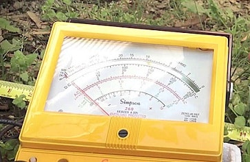
Soil Resistivity Type
Fall of Potential Earth Ground Test
This type of testing uses two stakes & also the electrode under test to confirm the proper system installation, and make sure the grounding system is already in position before building. To run a ground test through this technique, first, you have to confirm the ground electrode of interest is separated from the site.
If a current is generated by your 1625 Fluke, then the formed voltage will be connected simply to the external stake. After that, the voltage potential drop is measured between the internal earth stake & the earth electrode. By using Ohm’s Law, you will get a precise resistance measurement for the earth electrode. Connect the ground tester, press the START button, and read out the resistance value which is the actual ground electrode value under test.
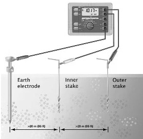
Fall of Potential Earth Ground Test
Earth Tester and Megger Difference
The differences between earth tester and megger are discussed below.
| Earth Tester | Megger |
| An earth tester is an instrument that is used for measuring low earth resistance. | Megger is an instrument used to measure high insulation resistances. |
| Earth tester includes earth electrodes which are used for measuring earth pit resistance, measured in ohms. | Megger is used for measuring an insulation resistance for electric motor winding of cable, measured in megaohm. |
| An earth tester is also known as a grounding resistance tester. | Megger is also known as Megohmmeter. |
| The Earth Tester includes two principal components; a rectifier & a rotating current reverser. | Megger includes different components like; a deflecting coil, permanent magnets, scale, control coil, pointer, battery connection/DC generator, current coil resistance, and pressure coil resistance. |
| Earth resistance tester simply measures low resistance. | Earth resistance tester simply measures high resistance. |
| By using this, the quality of insulation testing is not possible. | By using Megger, quality of insulation testing is possible. |
| It cannot function above its specific voltage. | It can function above its specific voltage. |
| Earth tester benefits are; that it checks that the installed security measures will work as expected in the occurrence of an electrical failure. Throughout this test, the exists resistance between the earth point of an appliance & the switchboard will be calculated. | Megger’s benefits are; it uses a DC Generator and a Permanent type Magnet. It doesn’t need any battery or some wire to connect. The physical damages can be recognized with megger that may avoid electrical shock because of leakages. |
Earth Tester Specifications
The specifications of the ERT-1501 earth tester include the following.
- This earth tester has data hold ability.
- It has a lock button for continuous hands-free measurement continuously.
- It displays test results & battery voltage on a similar display.
- This can be utilized within three-terminal & four-terminal configurations.
- The range of earth resistance is from 0 to 10/100/1000 Ohms.
- Its accuracy is ±3% + 2d.
- Its resistance range is low from 0 to 200 k.Ohms.
- It has four digits additional large size with a backlit dual LCD.
- Its DC voltage ranges from 0 to 1000V.
- It complies with CAT-III, CE 1000V.
- Its AC voltage ranges from 0 to 750V.
What is the use of Earth Tester?
The use of earth tester is to measure the resistance value of earth which is also known as earth resistance test.
How do you Measure Earth Tester?
There are some basic test methods used for measuring the earth tester like slope technique, star delta, clamp on the test, dead earth, three-terminal, and four points.
What is Earth Tester Megger?
The earth tester megger is generally a direct reading ohmmeter with hand hand-driven generator used to measure the resistance of the earth.
How do you Measure Earth Pit Resistance with a Multimeter?
To measure the resistance of the earth pit, need to set the multimeter to an AC volts range superior to your AC voltage supply. If you live in a 120 Volts area, then a 200v setting must be used. If you live within a 240v area, then a 500v/1000v setting must be used. Measure the voltage supply in between Earth & Neutral.
What Causes Grounding?
Grounding is the connecting procedure of a conductor to the earth which efficiently provides a stable & secure path for excess electricity to run away. This decreases the hazard of electrocution, electrical shock & fires caused by unexpected short circuits/voltage spikes.
Advantages and Disadvantages
The advantages of earth tester include the following.
- Earth tester helps in knowing the earthing condition from time to time.
- Earth tester is an effective and good system
- This test verifies the function of safety measures installed when electrical failure occurs.
- Earth resistance test helps in finding & reducing electric shocks & fires.
- This test ensures that the earth electrode system can efficiently dissolve fault currents, avoiding dangerous voltage buildup & protecting equipment & individuals.
- This test protects sensitive electronic devices like CNC machines from voltage surges & stray currents.
- This test supplies a low-impedance return path mainly for fault currents, so that they help in avoiding fluctuations of voltage, decrease electromagnetic interference & ensure constant electrical supply for sensitive equipment.
The disadvantages of earth tester include the following.
- Earth tester has inherent security problem that needs care as well as planning by the operator of the test set.
- When the earth test is in progress then a fault within the power system causes a high current to supply into the ground system.
- It is an expensive procedure.
- It consumes more time.
Applications/Uses
The applications of earth tester include the following.
- Earth tester is mainly used for measuring soil resistivity at different underground levels from ground level.
- This is used for Pad & Pole mounted transformers, Cell towers, telephone pedestals, protection from lightning, street lights & street cabinets
- This is used for sizing & projecting grounding grids.
- It is used to measure the motor’s winding cable’s insulation resistance.
- This tester helps in measuring the resistance of the earth terminal where the generated DC can be changed into AC through a current inverter.
- This is mainly designed to recognize & localize the junctions of high resistance which is very a common result of corrosion within exposed conductor systems.
Thus, this is an overview of earth tester or grounding resistance tester, construction, working, types, differences, advantages, disadvantages, and applications. The earth test meter produces an electrical current and after that, it supplies to the measuring electrodes. So the potential difference between the two electrodes provides information regarding the soil resistance value. Here is a question for you, what is the megger test?