 When commencing to explore the globe of electronics and electricity, it is very important to begin by understanding the fundamentals of voltage (v), current (c) and resistance (R). These three fundamentals are basic building blocks needed to employ and utilize electricity. At first, these concepts may be tough to grasp because we cannot see them. One cannot see with the eye the flowing of energy through a wire.
Even the lightning in the sky, whereas visible, isn’t really the exchange of energy happening from the cloud to the planet.However, a reaction within the air to the energy passing through it. So, as to notice this energy transfer, we should use measurement tools like a spectrum analyzer, multimeter and oscilloscope. This oscilloscope is used to visualize what is happening with the charge in a system. This article will give you the basic relationship and the difference between voltage and current and also relation between current and voltage
Relationship Between Voltage, Current and Resistance
The basic relationship between V, I and R in an electrical circuit is called Ohm’s Law. All materials are made up from atoms, each atom consist of protons, neutrons and electrons. Where protons have a +ve electrical charge, Neutron have no electrical charge and electrons have a –ve electrical charge. These three are together in the atom. But, if we separate them from each other they want to reform to exert a potential of attraction called a potential difference.
When we build a closed circuit, these electrons move and drift back to the protons because of their attraction to create a flow of electrons, this is called electric current. The electrons do not flow freely due to the restriction of flow of electrons, this is called as resistance.
Then all basic circuits comprise of three separate quantities, namely voltage, current and resistance.
Electrical Charge
Electricity is the movement of electrons, it creates charge which we can connect to do the work, your light, phone, stereo, etc. These all are operated using the basic power source that is, the movement of electrons. The three basic principles like voltage, current and resistance can be discussed using electrons or more precisely the charge they create. The main difference between current and voltage is, if a potential difference is applied b/n two points in any material, in principle, current can exist.
- Voltage is defined as, it is the potential difference b/n two points in electrical charge.
- Current is the flow of electrons
- Resistance is defined as, it is the tendency of a material to restrict the flow of current.
So, when we discuss about these values, the behavior of electrons in a closed loop circuit allows charge to move from one place to another. The major components used in the circuit let us to control the charge and use it to do the work.So, Bavarian scientist “Georg Ohm” was studied electricity. He described a unit of resistance which is defined by voltage and current. The difference between voltage and current and resistance is discussed below.
Please refer to this link to know more about Ohms Law MCQs
Ohm’s Law
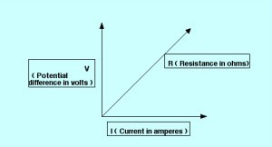
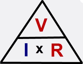
Ohm’s law is defined as, it is the relationship between three quantities such as resistance, voltage and current. It is derived by the formula V=IR Where,
Ohms Law
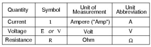
- Voltage V is measured in volts
- Current I is measured in Amps
- Resistance R is measured in ohms.
In this equation, voltage is equal to the current and that is multiplied by resistance. Using algebra methods, we can use this equation into two variations, for solving current & voltage, separately.
V=IR
From the above ohm’s law equation, we can calculate the current and voltage values by using the following equations.
I=V/R
R=V/I
In the below circuit, there are sources for voltage, resistance and current, namely the battery for voltage, the lamp is only one source of resistance and current. This makes it very simple to apply ohm’s law. If we know any two of the values of voltage, current and resistance we can calculate the third one using ohm’s law.
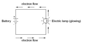
Basic Circuit Diagram of V, I and R
In the above circuit, when the voltage and resistance values are given, then we can calculate the amount of current. The amount of current in the above circuit is
V=12V, R=3 Ohms
I=V/R=>12V/3Ohms=4A
Difference Between Voltage, Current and Resistance
The main difference between these mainly involves what is definition of voltage, resistance and current.The differences between V, I and R are discussed below.
The voltage is defined as, it is the potential difference in charge between the two points on a circuit, it is also called electromotive force. It is measured in volts (1V = 1 joule/coulomb. (V=W/C)).One point has more charge than another. The unit volt is termed after invented by Italian physicist Alessandro Volta. The term volt is represented by the letter V in schematics. The measuring instrument of voltage is the voltmeter. Voltage is the source and the current is its result, it can occur without current. The voltage gets distributed over different electronic components which are connected in series in the circuit, and in parallel circuit voltage is same across all components which are connected in parallel.
The current is defined as it is the rate of flow of electric charge in a circuit. It is denoted with the symbol ‘I’. The unit of current is amps or amperage and 1 ampere =1 coulomb/second. The measuring instrument of the current is an ammeter. The flow of current is same in all the components which are connected in series. And, current gets distributed when components are connected in parallel.
Please refer to this link to know more aboutalternating current and voltage MCQs
The Resistance is defined as, it is the opposition that a substance offers to the flow of electric current. It is denoted by the letter R. The unit of resistance is the ohm, and the measuring instrument of the resistance is a multimeter.
Difference between Voltage, Current and Resistance
When describing the differences between the voltage, resistance and current by taking a common analogy is a water tank. Consider a water tank at a particular height from the ground. At the bottom of this water tank there is a tube. In this tank, charge is denoted by the amount of water, voltage is denoted by the pressure of water and the current is denoted by the flow of water. So for this, remember these terms: The charge is water, voltage is pressure and the current is water flow.
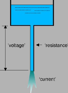
Common Water Tank
This is all about the relationship and the difference between voltage and current and resistance. Now you must understand the basic concepts of these three terms and how they are related. Ohm’s law is the basic principle for analyzing electrical circuits. Furthermore, if you are looking to study more complex applications of ohm’s law, please give your feedback in the comment section below. Here is a question for you, what are the instruments used for measuring the voltage, current and resistance.
Photo Credits:
- Baisc Circuit for V,I and R by allaboutcircuits
- Basic Water Tank by kevinboone