First of let’s begin with RVDT definition. The Rotary Variable Differential Transformer (RVDT) can be defined as a transformer which is capable to sense angular displacement and convert it into alternating current. This is basically a kind of electromechanical transducer which has ability giving linear output directly in proportional to that of the input of angular displacement.
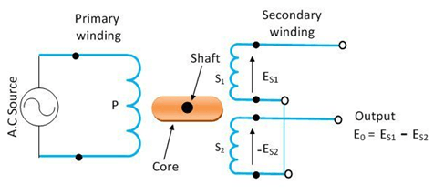
Circuit Diagram of RVDT
The following is a generic circuit diagram or RVDT construction having both primary and secondary wirings. The diagram is labeled with each component.
RVDT Theory Background and RVDT Mathematical Equations
Representing the secondary voltages with and which is changing with the extent in its angular displacement of the shaft of windings. The equation for its angle can be given as follows.
θ = G*((E_S1-E_S2)/(E_S1+E_s2 ))
Here G is a constant which is known as the constant of the sensitivity of Rotary Variable Differential Transformer. Here, the voltages at secondary windings can find out through the equation mentioned below.
E_S2=E_s1±G.θ
Now, the differential among is going to give proportionality constant which is mentioned below.
∆E_s=2.G.θ
Here, the sum of the voltages is given through a constant C. The formula of C is given as follows.
C=∑E_s=2.E_s0
Basic Operation of RVDT
The working principle of RVDT is almost the same as that of LVDT. The operation of RVDT is very simple, as whenever the core of transformer will be in null position, the output voltages of the secondary windings will always be and which are always equal in magnitude, however opposite in direction. The overall output of the null position is always going to be zero. In case of any angular displacement from the position of null will be giving the total differential output voltage. Therefore, it can be stated that the total angular displacement is always directly proportional to that of the differential output voltage while the response of the Rotary Variable Differential Transformer is always linear.

It can also be deduced that the differential output voltages of the RVDT are increasing whenever the shaft is rotating in the direction of clockwise and whenever it move or rotate in an anti-clockwise direction, the differential output voltages decreases. However, the magnitude of the output voltage is always dependent on the angular displacement along with the direction of the shaft.
Difference from LVDT
The only difference between RVDT and LVDT lies in the conversion and type of iron core used. The LVDT is using soft iron core and is sensing linear displacement for conversion into alternating current while RVDT is using cam shaped core and is sensing angular displacement for conversion into alternating current. The iron core in both LVDT and RVDT however, remains in the middle of the secondary winding.
Applications of RVDT
RVDT are extensively used in electrical systems. However, the following are some major uses of RVDT.
- These are used in navigation or flight control actuators.
- These transformers are used in valves or where fuel control is required.
- These transformers are used in cockpit controllers.
- These transformers are also used in missile fin actuation.
- These are also used in nose wheel steering systems.
Advantages of RVDT
The following are major advantages of RVDT.
- RVDTs are having lower sensitivity to temperature.
- RVDTs are less sensitive to variations in frequencies and voltages at primary winding.
- It has sturdiness nature, therefore best to be used in rugged applications.
- It has a small size, therefore best for applications which have space limitations.
- It has cost-effective structure and gives control, hence can be used in applications which are subtle and dedicated.