Truly, for the creation of a captivating field, a winding is required. This winding is associated with many titles based upon the point where it is provided. It is selected as a field winding if the winding is designed on the field poles. Likewise, it is defined as an armature winding if it is applied upon the focus. The winding is required for the creation of flux. This flux which in turn qualified for the creation of stability that allows needed twist for the turn of the rotor. Review what is an armature winding, types of armature winding, lap and wave winding, and applications.
What is Armature Winding
Definition: It is a type of winding that is housed in the slots of core and is responsible for the production of flux. The produced flux opposes the developed main field flux known as an armature reaction.
Pole Pitch of Armature Winding
The separation between the identical points of the adjacent pole. Pole pitch is mentioned in terms of electrical degrees. One cycle = 360 degrees I,e two poles per revolution. For 4 poles per revolution 2 cycles = 720 electrical degrees. P-pole /revolution = P/2 cycles.
Θelec = P/2 . θmech
Pole pitch is 180 electrical degrees and can also be expressed in terms slots, coil sides.
Pole pitch = 180 electrical degrees = S/P = 2C/P
Coil span or Coil Pitch
The separation between the top and bottom sides of a coil is called Coil span.
Back Pitch
The Separation between the top and bottom sides of a coil is known as back pitch and is represented by (Yb).
Front Pitch
It is the separation between the two coil sides which are attached to the commutator segment of the relevant coil side and is represented by (Yf).
Winding Pitch
It is the separation between consecutive sides of a coil or consecutive bottom sides of a coil and is represented by (Yw).
Commutator Pitch
It is the separation between the commutator segments to which two ends of the relevant coil is connected. It is represented by (Yc).
The back pitch, front pitch, winding pitch, and commutator pitch are shown in the lap and wave connection diagrams.
Types of Armature Winding
The winding of the machine is classified into two types. They are closed type winding and Open type winding. The classification of winding is shown in the figure below.
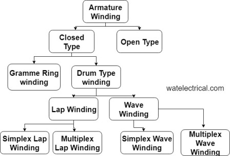
Classification of Armature Winding
The open type winding is further classified as
- Gramme ring winding
Gramme type winding is shown in the figure below.
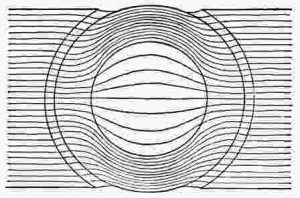
Gramme Winding
- Drum type winding
Drum type winding is shown in the figure below.
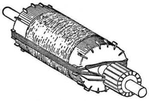
Drum Wound
The Drum type winding is further classified as
- Lap winding, and
- Wave winding
The Lap winding is classified as simplex lap and multiplex lap winding.
The wave winding is further classified as the simplex wave and multiplex winding.
Closed type of winding is that which starts and ends at the same location. The closed type of windings are used in commutator machines I,e in DC and AC commutator machines.
Open type of winding is that it is not closed at one end. These are used in AC machines like induction machines and synchronous machines.
In gramme type of winding, the emf will be induced in some portion of the winding the rest of the portion is left inactive. Due to this, there is a more non-conductive region in the gramme winding which is a disadvantage. Both the cost and weight of the machine increases due to the unnecessary non-functioning region. The figure which represents the gramme winding is shown in the figure below.
In drum-type winding, the whole part of the winding is conductive except at the end connections. As there is a more active length of the copper, the effective utilization of the copper is also more.
Lap Winding
In lap winding, the ending of one coil has connected the beginning end of the succeeding coil through commutator which is under the same pole. It is used for high current and low voltage applications. The figure which explains the lap winding is shown in the figure below.
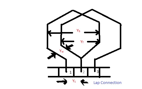
Lap Winding
In the case of lap connection, all the slots are completely filled. So, it is called a complete winding.
Simplex Lap winding
As winding moves from left to right when observed from the commutator point of view is called simplex progressive winding. In progressive lap winding, Yb > Yf
Wave Winding
In wave winding, the last coil is attached to the beginning end of the succeeding coil through a commutator which is under the beside pole. It is used for high voltage and low current applications. The figure which explains the wave winding is shown in the figure below.
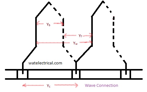
Wave Connection
In the case of wave winding, some slots are not filled completely. This causes some mechanical imbalance in the rotor. The life of the machine decreases due to this imbalance. So, in order to overcome this problem, the empty slots are filled by some dummy coils.
The dummy coils provide mechanical support to the rotor. These are also called dead coils. No energy conversion takes place inside the dummy coils and these are not connected to the commutator.
The tabular form of representation of the difference between the lap and wave winding is shown below.
Lap Winding | Wave winding |
| The number of parallel paths in lap winding is equivalent to the poles | The number of parallel paths = 2 |
| The number of brush required is equal to the number of poles | The number of brush required = 2 |
| Used for high current and low voltage applications | Used for low current and high voltage applications |
| Cost of lap winding is high | Cost is less |
| Efficiency is less | It is more |
| EMf is less | Emf is more |
| An additional coil employed is equaliser ring | The additional coil employed is the dummy coil |
Applications of Armature Winding
- Lap winding is used at low voltage and high current applications.
- Wave winding is used at high voltage and low current applications.
Thus, in this article, we had an overview of a winding. It is a type of winding that is employed in the slots of core and is responsible for the production of flux. This flux opposes the main field flux such that reaction takes place which is further used for the production of torque. Apart from this, we have also studied the different types of armature windings, lap and wave winding, and applications. Here is a question for the readers, what is the difference between a lap winding and a wave winding?
Leave a Reply