An electrical generator is a machine that is operated similar to operations performed by other machines. The main important function that it does is generating power. For this to occur, any machine requires a field that is able to develop some rotating field. This field is able to develop some torque that rotates the inner rotating part. For the production of this field, the employment of winding plays a key role. The field winding is placed on the stator while the armature winding is placed on the rotor. Due to the magnets, the magnetic line of flux is developed in the air gap. The conductors in the armature when get interacted with this magnetic flux, an armature flux will be developed. This armature flux is responsible for the movement of the rotor. Lets study armature, components, effects of armature reaction, Effects of Armature Reaction, and its applications.
What is an Armature?
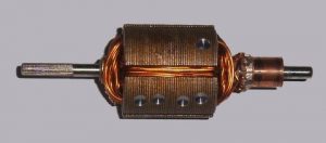
It is an important part of any machine that generates necessary torque for the movement of the rotor. The armature winding can be placed either on a stator or rotor. If the machine is to be operated with AC (alternating current), then the armature is placed on a stator. It is to be operated as DC (Direct current), then it is arranged on a rotor. This is the major constructional difference between an AC and a DC machine. The figure which depicts armature is shown in the figure below.

Armature
Armature Reaction in DC Generator
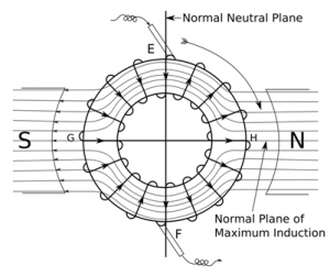
It is the opposition of flux produced by the main winding and armature winding. Simply, it is the opposition of armature and main flux. The field winding is arranged on the stator and armature winding on the rotor. The armature current produces the armature flux whereas the main poles produce the main field flux. The armature reaction diagram is shown in the figure below.

Effects of Armature Reaction of DC generator
The armature flux produces some effects on the main field flux whenever the two fluxes get interacted. The effects produced on the main field flux are of two types. One is the effect that distorts the magnetic field and the other weakens the magnetic flux.
Due to the distortion of the magnetic field, the generated voltage by the DC generator will get reduced. This distortion of the magnetic field is known as the Cross-magnetisation effect.
Due to the weakening of the magnetic field, the brush axis is to be shifted. But it is difficult to know the exact position of the magnetic neutral axis. This weakening of the magnetic field is known as the demagnetization effect.
GNA: It is the geometrical neutral axis which is perpendicular to the net flux produced.
MNA: It is the magnetic neutral axis at which no emf is induced in the armature conductors. Brushes and commutator are placed along this axis in order to overcome losses. The axis along which the brushes are placed is known as the axis of commutation.
Consider three cases to explain the effects of this reaction.
Case 1: At No-load, if only field current is considered. The figure depicts when only the field winding current.
At No-load, the GNA and MNA will be in the same alignment as there is no load. Only field flux will be present and the lines of flux will be left to right I,e from North to South pole. There is no flux developed by the armature as the armature current is zero.

Only Field Winding Considered
Case 2: If the only armature current is considered. The figure depicts when the only armature winding current.
Due to the armature current, armature flux is produced by the EMF caused in the armature conductors. This EMF is induced by the faradays law of electromagnetic induction. The direction of armature current in the conductor is determined by Fleming’s right-hand rule. The current in all the conductors get unified to produce a flux I,e the armature flux (ФA). The direction of flux is found by using corkscrew rule. The produced flux direction is downwards in this case.
Case 3: Demagnetisation Effect & Cross-magnetisation Effect
If both armature current and field current is considered. The figure which depicts both the armature and field current is shown in the figure below.

Both Armature and Field Winding
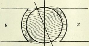
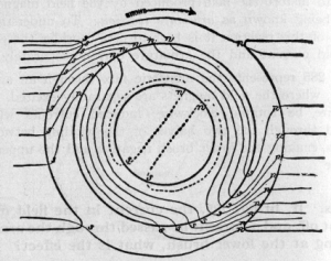
In this case, at ON-load both the armature and the field flux will act producing an armature reaction. Due to this, the resultant magnetic flux will not be uniform. It gets distorted at the lower pole tip of the North pole and South pole. Due to the distortion, the resultant flux and the MNA axis will also get distorted. The MNA is shifted by an angle (Θelec) in the direction of the resultant flux. The Brush axis is perpendicular to the MNA.
- Due to this non-uniform distribution of flux, resultant flux gets distracted and weakened. This distorted form of flux distribution is considered as the cross-magnetization and the weakened form of flux distribution is considered as the demagnetization effect.
- Due to the obtained resultant flux, the magnetic field gets distorted as shown in the figure. The overall field will be reduced which results in the degradation of voltage generated.
- Commutation problems arise due to the non-uniform distribution of resultant flux. As the brush axis is shifted due to the resultant flux. The brushes and commutator should be at no emf condition but due to the brush shift, the brushes will undergo a certain voltage which causes sparks in it.
Applications
- It is used for generating power.
- It is used as a rotor.
Thus, in this article, we had an overview of an armature reaction. It is the resultant flux obtained due to the opposition of armature flux and the field magnetic flux. Apart from this, we had also studied the working, effects of the reaction in DC generator, and applications. Here is a question for the readers, Explain the armature control method of DC generator?