Amplifier Circuit
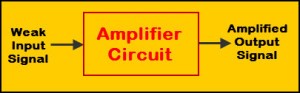
We generally use various types of electronic devices to design electronics projects or circuits. In some circuits or projects the output signals will be having low strength and are required to be amplified, to detect or use the output. Thus, the output signal can be amplified using amplifier circuits such as single stage transistor amplifiers, multistage transistor amplifiers, common emitter amplifier, and so on. But, what is amplifier circuit?
Amplifier Circuit
An electronic device or circuit that can be used for amplifying the signal (increases the signal power) is called as an electronic amplifier circuit or amp. An electronic circuit that can be used for controlling and amplifying the output signal to match (shape) and make stronger than the input signal is called an amplifier circuit. Amplifier circuits can be classified into different types based on amplifier stages, physical placement, representation of input (linear or nonlinear), and so on. Primarily, electronic amplifiers can be classified as voltage, current, transconductance, and transresistance amplifiers. But, these amplifiers can be realized using different transistor topologies. Our purpose here is to discuss about common emitter amplifier and its working in detail. But, primarily we must know about transistor amplifiers.
Transistor Amplifiers
An electronic circuit that consists of a transistor (as main component) along with other circuitry and is capable to increase the strength of the weak signal is called as a transistor amplifier. These transistor amplifiers are classified into different types such as single stage transistor amplifiers and multistage transistor amplifiers. In single stage transistor amplifiers, only one transistor and other circuitry are used for amplifying, whereas by connecting single stage transistor amplifiers together we can obtain a multistage transistor amplifier.
Common Emitter Transistor Amplifier
Transistor Amplifier Configuration
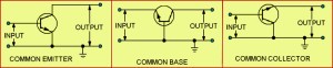
The most common configuration of transistor amplifier is a common emitter transistor amplifier which is typically used as standard format of transistor circuit where voltage gain is desired. The common emitter amplifier circuit is also termed as an inverting amplifier. The configurations of transistor amplifiers are common base and common collector transistor amplifiers as shown in the figure above.
Common Emitter Amplifier Characteristics
In the common emitter amplifier configuration, the base terminal acts as the input, collector terminal acts as an output, and emitter terminal acts as a common terminal for both output and input terminals. The common emitter amplifier is also called as a grounded emitter amplifier as the emitter is connected to the ground. Hence, this configuration is termed as common emitter configuration and common emitter transistor characteristics are as shown below.
- The voltage gain of the common emitter amplifier is medium
- The current gain of the common emitter transistor amplifier is medium
- The power gain of the common emitter amplifier circuit is high
- Input/Output is having a phase relationship of 180 degrees
- Input and output resistance of common emitter amplifier are medium
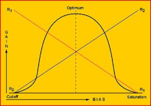
Bias vs Gain Characteristics
The above figure represents the bias vs gain characteristics of common emitter amplifier.
Common Emitter Amplifier Working
The common emitter amplifier circuit is shown in the figure below which consists of voltage divider biasing and is used to supply the transistor base bias voltage as per requirement. The voltage divider biasing circuit consists of the potential divider with two resistors connected such that their mid point is used for supplying base bias voltage.
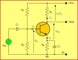
Common Emitter Amplifier Circuit
The common emitter amplifier consists of different electronic components that include resistors R1 used to determine forward bias, R2 is used to develop bias, RL is used for developing the output called as a collector load resistor, and RE is used for thermal stability. Capacitor C1 which is called as a coupling capacitor (including capacitor C2 that can be connected at the output terminal) which is used for separating AC signals from DC biasing voltage. As shown in the figure above bias vs gain common emitter amplifier transistor characteristics, if R2 increases, then forward bias will increase and R1 & bias are inversely proportional to each other.
If a weak signal (AC) is given to the transistor base of the common emitter amplifier circuit, then a small base current (AC) will start flowing. Thus, much larger current will flow through the collector through Rc (which is equal to β-beta times the base current). The voltage across resistance Rc is very this is because the resistor Rc value is very high (in the range of 4 to 10kOhm). Thus, a very high current appears in the collector circuit in the amplified form with the applied weak base signal. Hence, common emitter transistor acts as an amplifier circuit.
Common Emitter Amplifier Current and Voltage Gain
The ratio between collector current (change in collector current) and base current (change in base current) is equal to current gain and voltage gain is given by the product of current gain and ratio of output resistance of the collector circuit to the input resistance of base circuit.
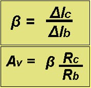
Common Emitter Amplifier Current Gain and Voltage Gain
Common emitter amplifiers are used as low frequency voltage amplifiers and are typically used in RF circuits (radio frequency circuits). These common emitter amplifiers are generally used as low-noise amplifiers.
Do you know the practical applications or electronics projects in which common emitter amplifiers are used? Then, please share your knowledge by posting in the comments section below.