It has been observed from the past twenty years that there happened many earthquakes all over the world which resulted in several fatalities and damages. These losses were because of the seismic excitation and resulted in both non-structural and structural catastrophes. So, it is important to enhance the seismic performance of the constructional structures. This can be done by implementing passive energy-dissipation and this provides improvised solutions for building structures and reduces the result of seismic activities. Since then the significance of damping has increased and now this article explains damping ratio, its formula, derivation, its significance, and related concepts.
What is Damping Ratio?
Damping is considered as the impact which is exhibited either internally or upon the oscillatory system which results in the elimination or reduction of oscillation. In the physical approaches, damping is generated because of the procedures that dissipate the accumulated energy in the oscillation. This is not dependent on the energy loss but sometimes it is even crucial in the case of other oscillating systems like those that happen in automobiles and biological systems.
Whereas damping ratio definition is expressed in the way that it is a dimensionless measurement that states how system oscillation will decay after having a disturbance. It can be observed that in many scenarios when a system is disturbed from its actual position of static equilibrium, then they show oscillatory behavior.
For example, the most observed scenario is the amplitude degeneration at the time of vibration in a singing bowl. The amount of decay is based on the extent of damping. The vibration amplitude has an exponential reduction corresponding to time.
The damping ratio symbol is given by ζ and this specifies the frequency response of the 2nd order general differential equation. Using the damping ratio, one can know the damping level of a system corresponding to critical damping. In the case of a damped harmonic oscillator having a mass of ‘m’, spring constant as ‘k’, and damping coefficient as ‘c’, then the damping ratio is defined between the system’s differential equation corresponding to the critical damping coefficient and it is represented by
ζ = c/cc = Actual damping /critical damping
And the system’s equation of motion is given by
m(d2x/dt2) + c(dx/dt) + kx = 0
and the critical damping coefficient is given by
cc = 2 Ökm
This can also be represented as
cc = 2m Ök/m = 2mωn
Here, ωn corresponds to the natural frequency of the system which is given by Ök/m
And ζ = c/(2Ömk)
This is the damping ratio formula.
Using the definition of damping ratio and natural frequency of the oscillator, we can write the system’s equation of motion as follows:
(d2x/dt2) + 2 ζωn (dx/dt) + ωn2x = 0
This is the basic mass-spring equation which is even applicable for electrical circuits as well. This is resolved as follows:
X(t) = Cest
Here, C and s represent complex constants. Where ‘s’ is given by
s = – ωn[ζ ± Ö1- ζ2]
Considering the above equation, there are many levels of damping and those damping levels are explained as below:
Undamped
For the situation ζ = 0, it represents an undamped fundamental harmonic oscillator and the result here is exp (i ωn t)
Underdamped
Considering both the + and – solutions for ‘s’ value, then every complex term is considered as a decaying exponential along with the oscillatory portion where the term is exp (i ωn Ö1- ζ2). This is the situation that occurs when the value of ζ lies between ‘0’ and ‘1’. This scenario is referred to as underdamped.
Overdamped
When the term ‘s’ is a couple of real values, then the result is a combination of two decaying exponential terms having no oscillation. This situation takes place when the value of ζ is greater than ‘1’. This scenario is referred as overdamped.
Critically Damped
Here, the value of ζ equals ‘1’ and this is the boundary condition in between underdamped and overdamped conditions. This is the result in many situations where the engineering design of a damped oscillator is necessary.
Damping Ratio in Control System
In a control system, the order of the system is known by the power of the term ‘s’ in the transfer function’s denominator part. For instance, when the power of ‘s’ is 2, then the order of the system is second order. The expression of the 2nd order control system is given by
C(s)/R(s) = ωn2/[s2 + 2 ζωns + ωn2]
Here ζ corresponds to the damping ratio and ‘ωn’ corresponds to the system’s natural frequency.
C(s) = R(s) {ωn2/ [s2 + 2 ζωns + ωn2]}
With this, the time response of the 2nd order control system can be known.
To know the damping ratio and its performance in the second-order system, the time response has to be known and it is explained as follows:
To know this, the open-loop transfer function ωn2/ [s (s + 2 ζωn)] is connected with a feedback loop that has a gain of one.
The transfer function of a closed-loop control system with unity gain in the negative feedback loop is given by
C(s)/R(s) = G(s)/[1+G(s)]
When the open loop transfer function is substituted, then
C(s)/R(s) = ωn2/[s2 + 2 ζωns + ωn2]
In the above equation, the power of ‘s’ is two and so the system is termed a second-order system. The characteristic equation is
s2 + 2 ζωns + ωn2 = 0
s = -ζωn ± ωn Ö(ζ2-1)
Considering the above equation, the damping ratio performance can be known,
- When the two roots are imaginary, then the damping ratio equals to ‘0’
- When the two roots are real and equal, then the damping ratio equals to ‘1’
- When the two roots are real but not complex, then the damping ratio is greater than ‘1’
- When the two roots are complex, then the damping ratio lies between ‘0’ and ‘1’
This is the procedure of how to find the damping ratio of a second-order system.
Damping Ratio of Closed Loop System
To know the performance of damping ratio in closed-loop systems, one has to contemplate multiple scenarios which are given below:
The system has to be completely stable in the open-loop state when we consider Bode graphs
When the phase cross over frequency is more than gain cross over frequency, then the closed-loop system is considered to be stable
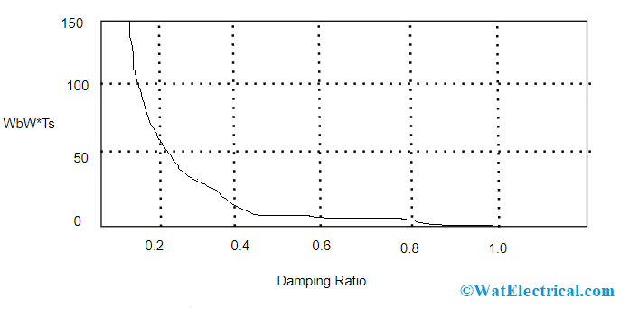
In the case of second-order systems, the damping ratio is nearly equivalent to the phase margin divided by 100 only when the phase margin value lies between 00 and 600. Here, the relation between settling time, bandwidth frequency, and damping ratio is
ωBW = ωn Ö[(1-2 ζ2) + Ö( ζ4-4 ζ2+2)]
ωn = 4/ Tsζ
ωBW = 4/ Tsζ2 Ö[(1-2 ζ2) + Ö( ζ4-4 ζ2+2)]
The below graph represents the relation between damping ratio and bandwidth frequency.

Damping Ratio v-s Bandwidth in Closed Loop
Significance
The amount of damping present in the system is used to know the oscillatory performance of a system. And this is the main significance of damping.
- When the spring-mass system is entirely lossless, then the mass oscillates without any pause. This situation is termed as undamped.
- When the system includes huge losses, for instance when the spring-mass is performed in a viscous liquid, then the mass gradually comes back to the static position without any overshooting. This case is termed to be overdamped.
- In general, the mass inclines to overshoot to its first position and then returns and after starts overshooting again. In every overshoot, a few of the energy gets dissipated and finally tends to ‘0’. This condition is called underdamped.
- In between the underdamped and overdamped conditions, there will be some level of damping where the system tends to overshoot and does not make even one oscillation also. This circumstance is called critical damping.
Percentage Overshoot
In the control systems, overshoot corresponds to the output which is more than the final steady-state value. In the case of step input, PO (percentage overshoot) is the maximum value with the difference of step value and divided by the step value. This is expressed as
PO = exp [- ζ δ/ Ö(1- ζ2)]
And the converse of this, damping ratio that produces a given PO is expressed as:
ζ = -ln (PO/100)/[Ö(π2+ln2(PO/100))]
Logarithmic Reduction
In the case of underdamped vibrations, the damping ratio also has a relation with the logarithmic reduction δ. The value of the damping ratio can be known for any two peak situations, even though they are not adjoining peaks. In the case of adjacent peaks, the damping ratio is
ζ = [δ/ Ö(δ2 + (2π2))]
Here, δ = ln(x0/x1)

Logarithmic Decreament of Damping Ratio
x0 and x1 are the amplitude levels of the two adjacent peaks
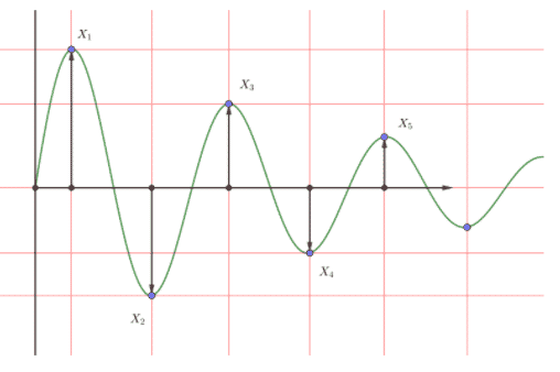
Based on the below picture,
δ = ln(x1/x3) = ln(x2/x4) = ln (x1 – x2/x3 -x4)
x1 and x3 are the amplitude levels of the positive peaks and x2and x4 are the amplitude levels of two negative peaks.
On a whole, this is the article on damping ratio. Here, the article explained on damping ratio in the control system, how to find the damping ratio in the control system, its significance, derivation, and related concepts. In addition, know-how the damping ratio is related to the second-order system?