Early 1830 Faraday worked on the process that is related to electromagnetic fields. He discovered a theory that is basic behind the working of a generator. Later several discoveries have been done that led to the invention of some other generators, those are the shunt, series, and compound type. However, all these types work on the same principle I,e the Faraday’s law of electromagnetic induction. So, the invention of the magnetic laws by Faraday behind the working of the generator has put an important mark on today’s life. In this article, we shall discuss what is a DC shunt generator, its working principle, emf equation, load test, characteristics, and applications.
What is a DC Shunt Generator?
It is a type of self-excited generator that has its field winding arranged in parallel with the armature winding. This type gives the constant voltage output and used for the charging of batteries. Since the field winding is connected in parallel with the armature it receives less current across it as it is wound with more turns and thin wire. Due to this, it is capable of producing fewer losses and it cannot be loaded eventually.
Working Principle
It also works on the principle of electromagnetic induction just like a normal motor. The field winding is connected shunt to the armature. When an input is given by the prime mover, the conductor is rotated in the permanent magnetic field. Due to this, the current gets induced in the conductors placed under the influence of the magnetic field. According to Faraday’s law of electromagnetic, an emf will be induced in the conductors when a conductor is rotated in the magnetic field. This induced emf is used to generate energy that is used by other mechanical devices. The current induced flow through the armature winding which is alternating. The output from the armature winding is always alternating and because of the commutator, the alternating current is converted to the direct current. This is how a direct current output is obtained in a shunt generator. The working diagram of the shunt generator is shown in the figure below.
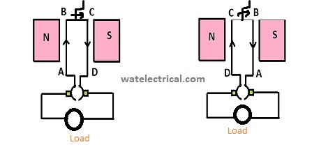
DC Generator Working
EMF Equation of DC Shunt Generator
The circuit diagram corresponding to the shunt generator is shown in the figure below.
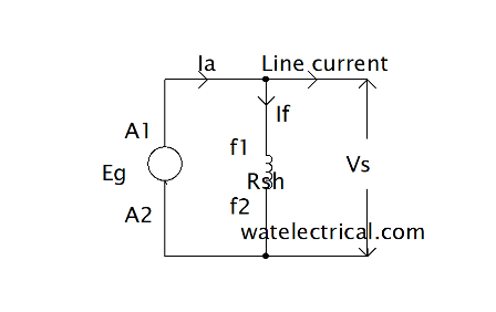
Shunt Generator Circuit Diagram
The emf equation corresponding to the shunt type generator is given by E = ФZNP/60A. From the circuit diagram, we can get Ia = IL + If
where
Z = number of conductors,
N = speed in rpm,
A = number of parallel paths,
P = number of poles,
Ф = flux per poles,
Ia = armature current,
IL = Line current,
If = field current. Line current can be further explored as Ish = V/Rsh
The induced emf is given from the circuit diagram as E = V + Ia R a = V + (IL +ISh )Ra
Load Test
A load test on a DC shunt generator is conducted to know the performance. It is done specifically to know the internal and external characteristics. The external characteristics are known by drawing a graph between the terminal voltage and the load current. The internal characteristics are known by drawing a graph between induced emf and the load current. The load test conducted on a dc shunt generator is shown in the figure below.
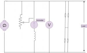
load test
Vary the terminal voltage up to its rated value with the help of adjustable rheostat and also adjust the load current value. Note down the readings of voltage and current with the help of voltmeter and ammeter connected to the circuit. The values of the terminal voltage and the load current are plotted in a graph as external characteristics and the values of emf induced and the load current as internal characteristics.
Please refer to this link to know more about DC Generator MCQs
Characteristics
The characteristics are classified as OCC and terminal. OCC is the open circuit characteristics drawn between the generated voltage and the load current whereas the terminal characteristics are drawn between the terminal voltage and the load current. The circuit diagram corresponding to the terminal characteristics is shown in the figure below.
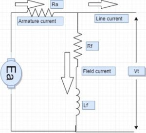
terminal characteristics circuit diagram
From the diagram, we get
VT = Ea – IaRa
If = VT/Rf
The field winding of the machine depends on the terminal voltage. As the load increases, the load current increases due to less resistance. We know that Ia = IL + If
From the equation, as the load current increases, the armature current also increases. Due to the increase in armature current, the armature drop increases I,e IaRa drop increases. If we put these in equation VT = Ea – IaRa We can observe that the terminal voltage gets decreased. From the equation If = VT/Rf
we can observe as VT decreases the field current If also decreases. Due to this, the flux value decreases all these values put together and drawn as a graph plotted between the terminal voltage and the load current as shown in the figure below.
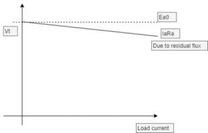
terminal characteristics Vt vs IL
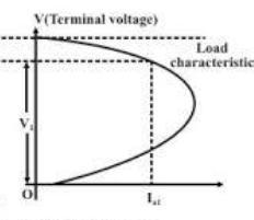
Terminal voltage vs load current
As when the load is attached and the generator is started with the help of a prime mover, it develops certain voltage due to the presence of residual magnetism. Due to this, residual flux is developed so the generated develops certain no-load voltage shown in the figure. As the load current increases, the voltage developed also increases and remains constant after reaching its saturation point. The resistance of the shunt type generator is linear, which is shown in the figure. The graph drawn between the generated voltage and the load current is shown in the figure below.
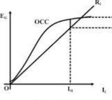
Eg vs load current
Applications
- Used in charging batteries
- for constant voltage applications
Thus, in this article, we had discussed what is a dc shunt generator. It is a type of self-excited generator whose field winding is connected in parallel with the armature winding and is used as a constant voltage generator that supplies energy for constant mechanical loads. In addition to this, we had also discussed its working principle, emf equation, load test, characteristics, and applications.