It is a general convention that in an electrical system, the current flow is always from higher concentration or potential area to that of lower concentration or potential area, for compensation which lies within the system. Practically, it is proven that the voltages at the transmission end are always greater to that of voltages at receiving end because of various line losses which depict the flow of current from supply to load.
S.Z. Ferranti introduced a theory in 1989, which was declared as an astonishing theory in electrical systems. The basic concentration of the theory was concentrated along medium distant transmission lines or the no-load operation of long-distance transmission lines. Sometimes the voltages at receiving end are in the level beyond transmission end. This is what the Ferranti effect in a transmission line is known in power systems.
Definition
The Ferranti effect can be defined as an effect in which the receiving end voltages gets higher at transmission line than that of the voltages at the transmission end. The effect may be occurring because of several reasons such as open circuit at reception end or because of the lighter load at the receiving end. The effect is because of the line’s charging current. Whenever an alternating voltage is applied at the line, the current produced is flowing across a capacitor and is known as charging current. The charging current is also given the name of capacitive current. The capacitive current is always increasing in the line whenever the voltages at receiving end are bigger than that of voltages at the transmission end.
The Ferranti effect definition can also be illustrated as the effect of voltage collection at the receipting end to be at a higher level than that of voltages at the transmission end. This kind of effect is generally occurring because of an open circuit or lighter load at the receiving end and may occur because of charging current at the transmission lines. The charging current definition is whenever an exchange voltage is linked, the current is flowing across a capacitor which is then named as the capacitive current. The charging current is always rising when voltages at the receiving end are greater than the voltages at the transmission end.
The Occurrence of Ferranti Effect
The lines are having two major parameters i.e. inductance and capacitance. The parameters are considered specifically for those lines having a length of over 250km. These lines are not having capacitance concentrated at specific points but is distributed over entire line uniformly. By the time when voltages are applied at the transmission ends, the current is drawn through the capacitance of the line which is more than current which is associated with the load. Therefore in light load or no load conditions, the voltages at the receiving end are higher when compared to transmission end and details are also available at Ferranti effect ppt online.
Parameters of the Ferranti Effect
As already discussed in detail how and why Ferranti effect is occurring, following are some additional parameters which needed to be considered as well and can be found in Ferranti effect pdf resources.
- The length of the transmission line is resulting in capacitance, hence cables having more capacitance than bare conductors. Long lines are having more capacitance than that of short lines.
- When the load is decreasing, the charging current is turning in to more important, whereas the decrease in load is increasing the voltages.
- The Ferranti effect is only occurring in large lines and where the connected load is light or there is a chance of an open circuit.
Calculation of Ferranti Effect
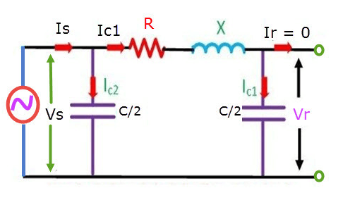
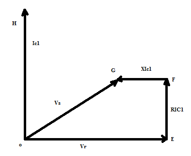
Let’s see the procedure for Ferranti effect voltage calculation. For the calculation of equations of Ferranti effect, considering a large transmission line having an OE signifying a collection of voltages, OH is signifying flow of current across the capacitor at collection end. The FE is phasor which is signifying a decrease in voltage through resistance, FG is signifying a decrease in voltage through inductance, OG is also a phasor which is signifying voltages at transmission end in a no-load condition. The following is the circuitry model known as the PI model depicting the entire scenario at no load conditions.

In the above PI model, OE is larger than OG and it can be stated that the voltage at reception end is greater than that of voltages at transmitting end and no load conditions are considered. The following is the Ferranti effect phasor diagram.

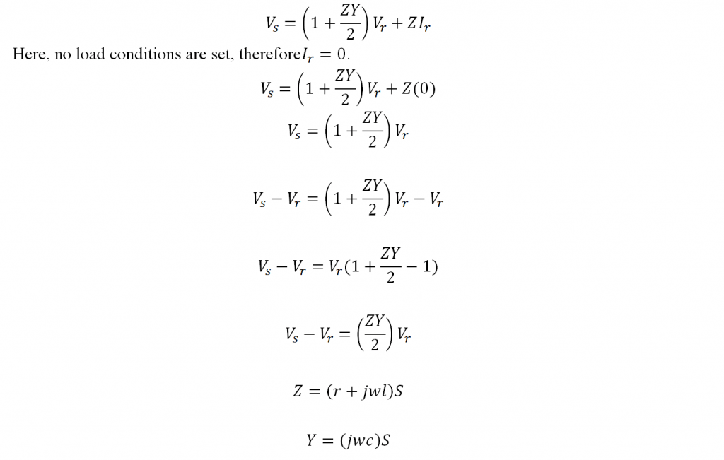
The equation for a small PI can be deduced as follows known as Ferranti effect equation.

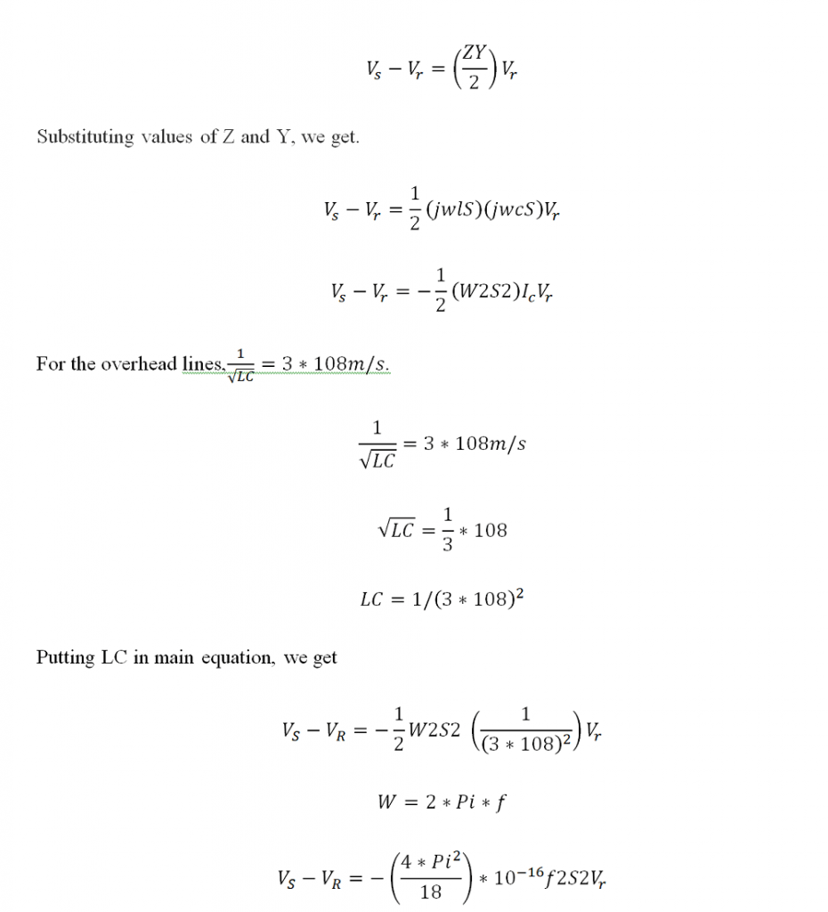
However in case if the resistance of transmission lines is neglected.

This equation is showing that is in negative value which means that the voltages at the receiving end are greater than that of transmission end. This is how the Ferranti effect calculation is undergone.
Ways to Reduce Ferranti Effect
The Ferranti effect in the power system is a common phenomenon. There are numerous disadvantages for Ferranti effect which affect the performance of the power system. Therefore Ferranti effect reduction is an important task to achieve i.e. how to reduce Ferranti effect in the transmission line. There are numerous ways for reduction of Ferranti effect, some of which are mentioned below.
It is already discussed that the inductance and capacitance are major parameters of the transmission lines which are in length larger than 240 km. These transmission lines are having capacitance distributed on various points all through the line but are not concentrated on a single point. Therefore, whenever voltages are applied on the transmission end, the current is being drawn by the capacitance of line and is associated with the load. Therefore, at no load conditions, the voltage at the receiving side is higher than that of transmission end.
Know more about shunt reactor.
All of the electrical machines are working on the electrical energy, therefore if the voltage is above the reference level at the consumer end, then the electrical machine may get damaged or the windings of the device might get damaged because of excess electrical spikes. The Ferranti effect is on the larger transmission lines having no load or lighter load, the voltages are increasing at the receiving end and this can only be protected through shunt-reactors used next to the collection end of the transmission lines.