A reactor or line reactor is a coil, used to protect the electrical devices & power transformers from the generated reactive currents throughout the fault conditions within the transmission. This reactor is generally made with an inductive material. The main function of the reactor is to restrict the reacting current that can harm the power transformer throughout the distribution or transmission within the substation. There are different types of reactors like series, shunt, damping, tuning, ARC suspension, etc. So these reactors have different functions which are used based on the requirement in the electrical power system like fault rectification, harmonics elimination, reactive currents, etc. So this article provides brief information on one of the types of reactor namely – shunt reactor – working with applications.
What is Shunt Reactor?
Electrical equipment that is used to stabilize the voltage throughout load differences within high voltage-based power transmission systems is known as shunt reactors. Usually, a normal shunt reactor includes a fixed rating that is connected directly to either the transmission line or to a tertiary winding of a 3-winding transformer. This reactor could be switched or connected permanently through a circuit breaker.
A shunt reactor is a compact device normally used for increasing the power and efficiency of the energy system because it absorbs & compensates the reactive power within long high voltage-based transmission lines & cables. As compared to a power transformer, this reactor is similar except it has single winding only for each phase.
Shunt Reactor Working Principle
The working principle of a shunt reactor is that it works like a reactive power absorber within an energy system for enhancing the system’s efficiency. To connect or switch this reactor To permanently, a circuit breaker (CB) is used. These reactors are extensively used in high-voltage energy-based transmission networks to control overload voltage differences. These reactors offer reactive power compensation depending on voltage requirements. Generally while operating these reactors, core losses may occur while designing these reactors, and special attention should be taken to reduce these losses.
Shunt Reactor Circuit
Shunt reactors are continuously used for EHV & long HV cables or lines. Shunt reactors are connected at both EHV line ends. The main reason to install these reactors at both EHV line ends is to avoid the line voltage from the exceeding design value once they are activated from one line end. Since there is some uncertainty usually as to which line end may be first energized or de-energized, these shunt reactors are connected at both ends of EHV lines. The following diagram will show the transmission line’s equivalent impedance П-Model including Switched Shunt Reactors at two ends.
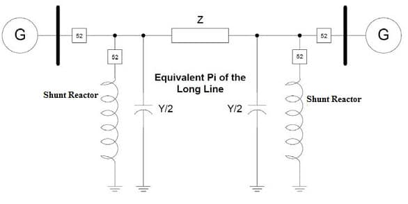
Shunt Reactor Circuit
This reactor could be connected or switched permanently through a circuit breaker or fixed shunt reactor. To enhance the reactive power utilization adjustment, the shunt reactor can also be variable.
The shunt capacitance mainly depends on different factors like the type of transmission line, transmission line voltage, and length. The shunt capacitance of a 345kV long-distance transmission line is approximately 3.14 Fµ/mile or 1.12Mvar/mile. For the 345kV cable, the equivalent shunt capacitance will be nearly 22.4Mvar/mile. So, by increasing the voltage of the transmission line, the shunt capacitance can also be increased. So the shunt capacitance is proportional to the square of the transmission voltage.
Types of Shunt Reactors
Shunt reactors are classified into two types based on construction: dry type and oil immersed.
Dry Type Shunt Reactor
Dry-type shunt reactor is normally limited to 34.5 kV of voltage. This voltage is normally given to the third winding of a transformer & is connected to the compensated transmission line. So these reactors are open to the atmosphere, air-cored & applicable for indoor/outdoor purposes. In most cases, the normal ambient air convection is used to cool the unit with arranged windings to allow airflow in between layers & turns which are supported mechanically by supporting elements or different materials like concrete, glass ceramics & polyester are used as supports.
Dry Type Shunt Reactor
This reactor is designed as a single-phase unit that is set over insulating pedestals or base insulators for providing insulation to the ground & also supporting the reactor. This reactor doesn’t have shielding although generates an external magnetic field with high intensity when it is turned on.
Thus, care is necessary for specifying the clearances as well as the reactor unit’s arrangement, station structure, mounting pad & any metal area around the reactor or in the closeness of the reactor.
A closed metallic loop in the surrounding area of this reactor generates heating, losses & arcing at poor joints; so, it is significant to neglect these loops & also to maintain enough separation distances.
Shielding is necessary when it is not feasible to place dry-type units within an equilateral-triangle arrangement separated from outside magnetic influences. So this shielding is necessary to restrict the impedance difference between phases. For reactors, the difference in impedance values will result in a difference from the definite MVAR rating.
The main benefits of dry-type air-core reactors are operating costs, lower initial, lower losses, lower weight, its maintenance & nonexistence of insulating oil. The main drawback of this type of reactor is kVA ratings, limitations on voltage & external high-intensity magnetic field.
Oil-Immersed Shunt Reactor
Oil-immersed shunt reactor is mainly designed like 1-phase or 3-phase units. These reactors are very similar to conventional power transformers in external appearance. These are intended for either forced cooling or self-cooling.
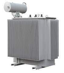
Oil Immersed Type
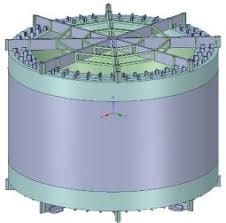
These reactors are designed in two configurations like coreless type & gapped iron-core type. But the gapped iron-core type design is subject to more severe energizing inrush as compared to the coreless type.
Shunt reactors with a coreless design have a magnetic shield that is used to surround the coil to hold the flux in the reactor tank. Normally the steel core-leg provides a magnetic flux lane throughout a power transformer coil that is replaced with insulating support structures.
The designing of the magnetic shield of a gapped iron-core reactor is done very similarly to a power transformer except that little gaps are introduced within the iron core to enhance the linearity of the reactor’s inductance & also to decrease remanent flux or residual as compared to a reactor devoid of a gapped core.
Measurement of Losses in Shunt Reactor
In shunt reactors, the losses at both frequency and rated voltage must be determined. But, assembling of high test voltage during the losses measurement for a shunt reactor with an extremely high voltage type may be hard. Thus, by detecting the measurement losses of the reactor, complications can be reduced at a less voltage as compared to the system voltage of the reactor.
After that, the observed loss can be multiplied by the square of the reactor current & proportion of the rated current to attain the loss at the rated voltage & decreased test voltage. Once the shunt reactor’s power factor is low, then the measurements of conventional wattmeter loss are not reliable; in its place, a bridge method may be used for measurement & better precision.
In the different parts of this reactor, the measurement losses cannot be separated through this test. To avoid the test correction resulting from a reference temperature, it is better to obtain the measurement when the usual temperature of the winding is equal to the reference temperature.
Difference between Shunt Reactor & Power Transformer
The difference between a shunt reactor and a power transformer includes the following.
| Shunt Reactor | Power Transformer |
| The shunt reactor is intended to consume reactive VArs to enhance the efficiency of the system. | The power transformer is mainly designed to transfer efficient power from one voltage system to other. |
| This reactor includes only a single winding. | This includes more than one winding with a magnetic core that carries mutual flux in between these two windings. |
| In this reactor, all primary ampere turn (AT) is equivalent to the exciting ampere turn because of the nonexistence of other windings, Like a power transformer, the loss within AT is also kept to the lowest by design. | In this Transformer, the main AT (ampere-turns) is the sum of exciting & secondary AT. The exciting ampere turn is very small as compared to the secondary AT. |
| These are classified into two types dry type & oil-immersed type. | These are classified into different types like berry type, shell type, core type, isolation, step up, step down, single phase, three phases, auto, etc. |
| The characteristics of the shunt reactor include power factor, thermal rating, impedance & audio sound level. | The power transformer characteristics are; these are big in size, the core shape is either shell or core type, short flux path, restricted to low range frequencies, etc. |
| It is designed without an iron core or air to avoid hysteresis loss because there is a huge amount of magnetizing current. | These transformers don’t contain a huge amount of magnetizing current. |
| These are simply rated in MVAr. | These are simply rated in kVA. |
Characteristics
The most significant shunt reactor characteristics mainly include; Impedance, Thermal rating, and audio sound level.
Impedance
The shunt reactor should have a constant impedance of approximately 1.5 times the rated voltage to avoid the generation of harmonic current under over-voltage conditions of the system. In addition, this impedance must be balanced precisely between phases of the three-phase reactor.
Thermal Rating
These reactors are capable of continuously operating at a voltage without exceeding 1500 C hot spot temperature at any element of the reactor. Once the shunt reactor is working at 420 KV, then the temperature will be increased.
Vibration and Audio Sound Level
The design of the reactor should make sure a minimum range of noise & vibration during the constant working of the reactor. So, care should be taken to make sure that the natural vibration period is on either the tank shields or the yokes so that they will not vibrate once the shunt reactor is excited at its rated frequency. The level of audio sound should not beat the normally accepted for the same MVA & voltage rating transformers.
Applications
The applications of shunt reactors include the following.
- Shunt reactor is used in high voltage energy-based transmission systems for voltage controlling throughout load differences.
- These reactors are switched ON.OFF based on the needs of voltage required to give reactive power compensation.
- These are used in high-voltage systems & cables network to enhance the efficiency of the system.
- It works like a reactive power absorber to enhance the energy efficiency of the system.
- These reactors are applicable in different systems like HV & EHV.
- It is used to enhance the efficiency of energy & power systems because it absorbs & compensates for reactive power within cables & transmission lines.
- The variable shunt reactor type is used to optimize the current network condition dynamically as well as the voltage within the network.
- By using these reactors, network stability can be enhanced & also provides incessant voltage regulation in the low-load otherwise no-load operation of the transmission lines.
- These are used to improve the power quality & voltage stability.
Know more about Power Triangle.
Know more about Two Port Network MCQs, Vacuum Circuit Breaker MCQs.
Please refer to this link for Shunt Reactor MCQs.
Thus, this is an overview of a shunt reactor which is widely employed in AC networks to limit shortcut current or overvoltage within power transmission. This reactor plays a key role in increasing the efficiency of the grid & stabilizing network systems. These are rated with power from 33 kV – 800 kV (≤10 MVAr – 300 MVAr). Here is a question for you, what is a series reactor?