In the domain of electronics and electromagnetism, inductance is the crucial concept where it is the inclination of a conductor to contradict the current flow. The current flow generates a magnetic field across the conductor. The field strength is based on the current’s magnitude and goes as per current changes. The word inductance was coined by Oliver Heaviside in the year 1886. In the name of Heinrich Lenz, the symbol of inductance was provided. The story of electromagnetic induction is a component of electromagnetism initiated with the interpretations of electric charge, electric current, and magnetic attraction. By knowing the concord of these forces in nature and the scientific concept behind electromagnetism started in the 18th era. The one prominent concept that arrived with this interpretation is Mutual Inductance. This article is completely focused to explain its working, derivation, formula, dimensions, and corresponding applications.
What is Mutual Inductance?
Mutual induction definition is stated that when two coils are brought in close with other than the magnetic field in any of these two coils direct to connect with the other coil. This directs to the development of voltage in the second coil. This scenario of one coil that impacts or modifies the voltage and current values in the other coil is called a mutual inductance property.
Mutual inductance can impose few bad things also which are leakage and stray inductance. When these are released from one coil, they affect the functionality of another element through the process of electromagnetic induction. Because of this, some approach of electrical screening to a minimum potential might be necessary.

Mutual Inductance Phenomenon
The extent of mutual inductance which connects one coil to another is based very much on the corresponding location of both the coils. When one coil is located next to the adjacent coil then that their physical distance apart is minimal, then approximately the entire magnetic flux developed by the first coil will have a connection with the coil turns of coil 2 consisting of a comparatively large emf and so generating huge mutual inductance value.
In the same way, when both the coils are beyond apart from one other or placed at various angles, then the amount of developed magnetic flux from coil 1 into coil 2 will be lower generating a much minimal induced emf and so a very minimal mutual inductance value.
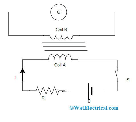
The mutual inductance theory can be known through below example:
Consider two coils ‘A’ and ‘B’ which are close to one another. When the switch is closed state, it allows the current flow and this develops magnetic flux in the ‘A’ coil and EMF is generated in the coil and when there happens a change in the current value by altering the resistance, the flux coupling with ‘B’ coil also gets change due to the altering current. So, this scenario of flux linkage between two coils ‘A’ and ‘B’ is termed as MI. The mutual inductance formula used for measuring the amount of mutual inductance developed between two coils is given by
em = M (dI1/dt) or M = em/[(dI1/dt)]
With the above formula, the magnitude of mutually generated EMF in the coils and current change value in the other coil is also known. When em is 1 volt and (dI1/dt) is 1 ampere, then from the above equation, the MI value equals 1 Henry which is the SI unit of mutual inductance.
So, it can be stated that when two coils are defined to have a mutual inductance of 1 unit of Henry when the EMF of 1 volt is generated in one coil or else it can be stated that primary coil when the current flows through the other coil is altering at a rate of 1 ampere for every second.
Mutual Inductance is even defined in the following approach which is that
em = M (dI1/dt) = d/dt [MI1]
em = N2 (dϕ21/dt) = d/dt [N2ϕ21]
By solving the above two equations, then
MI1 = N2dϕ21
M = N2dϕ
21/I1
This equation is utilized when the flux linkage of one of the coils because of the current that flows across the other coil is identified. The mutual inductance is based on the factors of cross-sectional area, vicinity of both the coils, and turns present in the secondary coil.
This is the mutual inductance derivation, and the unit of mutual inductance is Henry.
Mutual Inductance of Two Coils
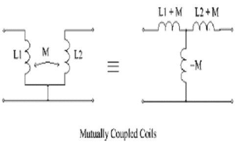
The MI which is present in between the coils is enhanced by placing both the coils on the same soft iron core or else by augmenting the turns present in either of the coils as in the transformer. When both the coils are rigidly connected on the top end on the same soft iron core then there exists unity coupling across them because any kind of losses because of flux leakage will be very minimal. Then, supposing an ideal flux linkage between the coils and the MI for two coils is represented as follows:

Mutually Coupled Coils
M = [µ0µrN1N2A]/l
In the above equation,
µ0 corresponds to the permeability of free space which is (4π10-7)
µr corresponds to soft iron core’s relative permeability
‘N’ corresponds to the number of coil turns
‘A’ corresponds to the cross-sectional area which is measured in m2
‘l’ corresponds to the length of the coil which is measured in meters
Mutual Inductance EMF
As per the above discussion, the mutual inductance between two coils is given by
M21 = N2ϕ21/I1
M21 I1 = N2ϕ21
When current changes with respect to time, then
M21 (dI1/dt) = N2(dϕ21/dt)
As per Faraday’s law
ϵind = -(dФ/dt)
So, it can be resolved that
M2(dI1/dt) = – ϵ21
Then, induced EMF in coil 2 because coil 1 is shown as
ϵ2 = -M21(dI1/dt)
In the same way, induced EMF in coil 1 because of altering current in coil 2 is provided by
ϵ1 = -M12(dI2/dt)
With all the equations, M21 = M12 = M
So, ϵ1 = -M(dI2/dt) and ϵ2 = -M(dI1/dt)
Coupling Coefficient
In general, the inductive coupling present in between the coils is represented as a number that lies in between the values 0 and 1 other than representing in percentage values. So, ‘0’ represents that there is no inductive coupling and ‘1’ indicates the highest inductive coupling.
When the value of ‘k’ is 1, then there exists perfect coupling between coils, and when k is more than 0.5, there is rigid coupling between coils whereas when k value is below 0.5, then there is minimal coupling between coils. The equation that is defined for perfect coupling can be altered to consider this coupling coefficient ‘k’ is shown as coupling factor between coils and is represented as
k = M/(sqrt(L1L2)) or M = k(sqrt(L1L2))
When k = 1, it means that the flux lines in coil 1 cut the entire coil 2 turns which represent that both the coils are rigidly coupled to each other and the final mutual inductance equals to mean value of the mutual inductance of two coils calculated separately. Additionally, at the condition when L1 = L2, then the mutual inductance present between both the coils equals to the value of either of one coil and shown as a single value which is given by
M = sqrt(L1L2) = L
MI of Coaxial Solenoid
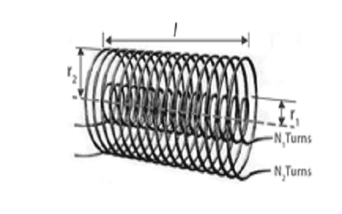
To know the mutual inductance of a coaxial solenoid, consider two coaxial kinds of solenoids where the radius of two are given by ‘r1’ and ‘r2’. The turns in both the solenoids are ‘N1’ and ‘N2’. The length of the two solenoids is equal.
When a current of I2, flows in the S2 solenoid, then MI in S2 is given by
B2 = µ0n2I2 = (µ0N2I2)/l
The related flux linkage in S1 is
N1φ12 = N1 B2. A1 N1 φ12 = (N1µ0N2I2)/πr2
Also, N1φ1 = M12I2
On comparing the above two equations, we get
M12 = (N1µ0N2πr2)/l
In the same way, when a current of I1 flows across S1, then the induced magnetic flux in S2 is given by
N2φ21 = M21 I1
N2φ21 = N2 B1. A1
N2φ21 = (I1N1µ0N2πr12)/l
M21 = (N1µ0N2πr12)/l = M12 = M
Applications
A few of the applications of MI are as below:
- Used in electric motors and generators
- Implemented in the functionality of digital signal processing
- Used in transformers – A transformer is the main component that works on the principle of mutual inductance and this is constructed for the application of converting alternating current from one level of voltage to another level. Through mutual induction, the magnetic flux of either two or more inductors gets connected. And because of this, the voltage induction takes place in one coil which has direct proportional relation with the rate of change in the value of current in the other coil. And the transformer is the device which is designed with two or more inductors where one of those inductors gets power supply from AC, thus developing AC voltage in the second inductor
- Utilized for the calculation of eddy currents
This is all about the concept of mutual inductance where it is used in various applications across multiple domains. This article has explained Mutual Inductance derivation, its coupling coefficient, its relation between two coils, EMF of MI, and applications. To have a more clear idea of this concept, consider what are the examples of mutual inductance and how they are resolved?
