In the early 1880s Oslen proposed to test the machine to invent some new and improvements in machines. In his proposal, he highlighted the difficulties he faced running any machine. Accordingly, he also proposed certain measures to be taken to avoid such difficulties. He suggested testing the machines to improve their performance and working difficulties. So, this is the reason why a machine is tested by different methods to know its behavior. There are different methods used for this testing we shall discuss those in this article. In this article, we shall also discuss the different testing methods used for testing of DC machines.
Testing Methods of DC Machines
Basically, the testing of DC machines classified into two types. Namely, direct and indirect tests. The indirect test is further classified into two. They are Swinburne and Hopkinson’s Test. The classification chart of testing DC machines is shown in the figure below.
Direct Test
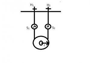
A direct test is applicable for small machines where some amount of load is applied to the machine. After applying the load the voltage and current values are noted. By analyzing these values, we can conclude the application of machine. The applied load on a machine is shown in the figure below.

Direct Test
In the figure above, it is shown that a load is applied to the shaft of a machine by two handles arranged at the top. These handles H1 and H2 are used to tighten the belt which is attached to the pulley of the machine. These two handles are supported by two springs S1 and S2. Whenever the handles are twisted some load is put on the pulley and this force is measured by the springs S1 and S2.
By applying different types of loads on the machine the efficiency is calculated. The efficiency is determined by the formula below.
The efficiency of the machine Ƞm = (w (S1 – S2) 9.81) / VtIl * 100
where S1 and S2 = Spring force
Vt = terminal voltage,
Il = Line current, and
w = weight.
There are some drawbacks to using this method. They are
- Applicable to small rated machines only.
- Spring force is not constant, and
- Handles cannot impart a constant frictional force on to the pulley.
Indirect Test
- Swinburne and
- Hopkinson’s Test
Swinburne Test on DC Shunt Machines
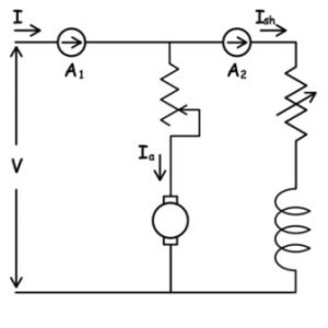
This test is mainly applicable for conducting a No-load test. DC shunt machine is the best option for conducting No-test. During the No-load test, the current directly appears across the field winding of the DC series machine which results in the burning of winding. So, considering this case a DC series machine is not used for this test. Hence, the DC shunt is the best option as the field winding is connected in parallel to the armature. The circuit diagram that depicts the Swinburne test is shown in the figure below.

Swinburne Test
This method is best suitable for testing at No-load. It can be operated for large machines. The drawbacks of a direct test are overcome in this method. An ammeter is connected in series with the machine to find the current and the field winding in parallel with the armature. The parallelly fed field winding is connected with a variable winding such that as it is varied the current in the armature changes. This change is noted by observing the ammeter reading. Different readings are noted by varying the load at different points.
By this method efficiency at any point can be determined and this method is suitable for large-rated machines. But there are some drawbacks to this machine, it cannot determine stray load losses exactly.
Hopkinson’s Test
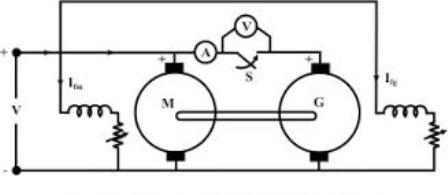
Hopkinson’s test is also called a Regenerative test as a regenerative process takes place during this process. The drawbacks of the Swinburne test are overcome by this test. The circuit diagram that depicts regenerative testing is shown in the figure below.

Hopkinson’s Test
This can be applied for even small and large-sized machines which are a great advantage. This method is applicable to even conduct testing at rated load. As the testing is suitable for rated load conditions, we can able to determine the efficiency at rated loads and also able to determine the stray load losses. Since at rated loads, we can determine the copper and armature losses exactly.
From the figure, we can observe that the motor and generator are coupled together. Initially, DC supply is given to the motor as the motor begins to rotate it further also initiates the generator also to rotate. The switch between the motor and generator is initially open. After the initial rotation of the generator, it is switched ON such that the current from the generator is carried to the motor. This is the condition which is actually a regenerative action. Therefore, it is considered as the regenerative testing method. The ammeters are connected at each point of the machine such as at the armature of motor and generator and also in series with the field windings. The field windings are connected in parallel with either of the machines (motor and generator) to vary the load. As and when the load has varied the currents in these ammeters are to be noted and tabulated.
The currents at different variations of load are noted to determine the efficiency and stray load of the machine.
Thus, in this article, we had discussed the different methods of testing the DC machines. These methods are used for testing to determine the performance of the machines at different load conditions to determine its usage at a suitable location. The different testing methods used are the direct test, Swinburne, and regenerative testing. Each type of method has its individual impact. The most important method among these is regenerative testing. Here is a question for the readers, What is the use of the Swinburne test and what is determined by conducting this test?