The first commutator was invented by William sturgeon using the machine in the year 1837. After that, an American inventor namely “Thomas Davenport” was invented another commutator type DC machine and afterward, AC machines are invented. This machine is used to control the devices which operate using alternating current. A DC machine is used to operate the devices which use unidirectional current. When we evaluate with DC machines, Alternating Current machines have more advantages because of the losses that appear in DC. Though the losses are more, DC machines find its importance in modern day to day life. It has its unique feature of generating unidirectional current. So, these machines are used at a place where there is a requirement of single directional power. These machines are used in batteries to generate unidirectional power. This article gives an overview of a DC machine, which includes construction, working, parts, EMF equation, types, its losses, and applications.
What is a DC Machine?
It is a rotating device which can be either a motor or a generator. Depending upon its construction and operation it is classified as a motor or a generator. A motor is a device that converts electrical energy into mechanical energy. A generator is an electrical device that is used to convert energy from mechanical to electrical.
Construction
Parts of the machine
It consists of a Yoke, pole core, pole shoe, armature core, commutator, brushes, bearings, and fan.
The yoke is used for the protection of the device from outer environmental issues. It is used as a shield to protect the inner parts of the machine. It provides mechanical support to the inner parts of the device.
Pole core consists of pole shoe, and field winding rests on the pole shoe. The pole shoe with field winding is inserted into the slots of the pole core.
In the machine, the two essential parts are the stator and the rotor where the stator is the stationary part and the rotor is the rotating part. There are two windings in this machine namely field winding and armature winding. The arrangement of these windings can be done like this, the field winding is arranged on the stator whereas the armature winding is arranged on the rotor. However, in an AC machine, the arrangement is reversed to the ac machine. This is the main difference between a DC and AC machine. The DC generator construction is shown in the following diagram and its parts are shown.
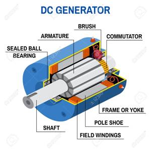
Parts of DC Generator
Armature core consists of armature winding, which rests on the slots of the core. It consists of slots which are teeth type such that the armature winding can be inserted into the slots easily.
A commutator is a device that is used for the collection of current from the armature winding whereas the brush collects the current from the commutator.
For the smooth operation, bearings are used. A fan is employed to remove the heat generated during the operation of the machine.
It’s Working
DC machine works on Faraday’s law of electromagnetic induction principle, which states that when a conductor cuts the magnetic lines of forces then an electromagnetic force will be induced within the conductors.
In a DC generator, when the coil placed in the magnetic field is rotated by means of a prime mover or any handle. The coils cut the magnetic lines of forces to induce an EMF. This induced Emf develops current in the armature winding. The direction of this current in DC generators can be observed through the rule of Fleming’s Right-hand. The DC generator working image is illustrated below.
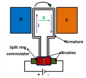
Working of the Generator
The current in the coil changes every half-cycle as the coil rotates which is found by Fleming’s Right-hand Rule. Due to this, an alternating current is developed which is detected by a galvanometer. So, in order to obtain a unidirectional current, commutator segments are attached to the brushes. These segments generate unidirectional current as the coil rotates. The segments run smoothly between the brushes and do not allow the current to alter. As the coil is rotated, at the half rotation the segments rotate between the brushes but do not allow the current to change its direction. Thus, this is how a DC generator is able to convert the input mechanical energy into a DC output electrical energy.
The working of a DC motor and a generator is similar however here a DC supply is given to the armature winding. Due to this, current flows in the coil placed under the magnetic field. Whenever a coil that carries current is arranged beneath the magnetic field’s influence which experiences a force. The direction of the force can be found with the help of a rule namely Fleming’s Left-hand. The DC motor working diagram is shown below.
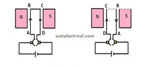
DC Motor Working
The role of a commutator in DC motor is very important. As the coil rotates it cannot develop unidirectional torque because the force acting is not uniform. The current in the coil at the left end is inwards and force acts upwards by fleming’s rule. The current in the coil at the right end is outwards and the force acts downwards. This force allows the coil to rotate in the clockwise direction. But, after half rotation, the force at the left end will act downward due to the change in current. And the force at the right end will act upwards due to the change in current.
So, in order to develop a unidirectional torque, the force should be uniform and it should act in one direction. Then only the coil can be able to rotate in the clockwise direction. This is achieved by using a commutator, it consists of segments attached to the brushes. These segments allow the current in the coil to be in the same direction as before. Then, the force will be acting upwards at the left end and downwards at the right end continuously. This allows in developing a torque which is uni-directional will activate the motor to work continuously.
EMF Equation of DC Machine
The EMF equation is given by E = ФZNP/60A
Let
P = no of poles
Z = no of conductors distributed in the armature
Ф = flux produced by each pole in weber
N = speed of the rotor in r.p.m
A = no of parallel paths
The induced emf within the armature conductors is according to the faradays law of electromagnetic induction.
where e = rate of change of flux , e = dФ/dt
Total flux produced (ФT) or (dФ) = flux produced by individual pole * no of poles
(ФT) = Ф * P
The time required for a conductor to complete one revolution (dT) = 60/N
substituting these values in emf induced, we get
e = Ф * P / 60/N
e = Ф * P *N/ 60 for one conductor
e = Ф * P *N *Z / 60*A for ‘Z’ conductors for ‘A’ parallel paths
Therefore, the EMF equation is given as e = Ф * P *N *Z / 60*A
Armature Reaction
The opposition of the main magnetic flux by the developed armature flux is known as Armature Reaction. The induced EMF is developed when the coil is rotated in the magnetic lines of forces. This induced EMF allows current to flow in the armature winding as the winding is a closed circuit. This armature current with further interaction with the magnetic lines of forces develops armature flux. This armature flux is used for the generation of the armature reaction. Due to this, a unidirectional torque is developed that is used for the rotation of the rotor. The Armature Reaction of this type of machine is shown in the following image.
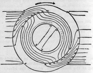
Both Armature Field Winding Considered
There are certain drawbacks due to the armature reaction also. It distorts or weakens the magnetic flux that results in the reduction of generated voltage in the case of a generator.
Commutation in DC Machines
The Commutation is the process of changing the form of alternating voltage or current to the single directional voltage or current and vice-versa.
It consists of some segments which play a crucial role in this conversion process. The commutator segments are mainly used in the DC machines. It is made of Mica that acts as an insulation material between the two segments. It has high dielectric strength and breakdown strength of nearly 30 to 40V.
These are used after the armature to collect the current from the armature winding. Either of the segments is connected to the brushes which are used to collect the current from these segments. The commutator segments with brushes are illustrated in the below figure.
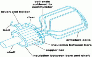
Commutator Segments in DC machines
In this type, the commutator segments help in avoiding the twisting of the wires while the rotor is rotating.
In the DC generator, the commutator is used to change the alternating voltage or current that is generated into a single directional voltage or current.
In DC motor, the commutator segments play a key role in producing a unidirectional torque. These segments are used to alter the current in the coil so that a unidirectional torque is developed. And the motor is able to rotate in the clockwise direction.
Losses in DC Machine
There are three types of losses in the machine. They are
Copper losses, Iron losses, and stray losses.
- Copper losses are classified into three armature, shunt field, and series field copper losses.
- Iron losses are classified into two, one is Eddy current, and the other is hysteresis losses.
- Stray losses are classified into two, one is frictional, and the other is windage losses.
The figure which explains the classification of losses in the machine is shown below.
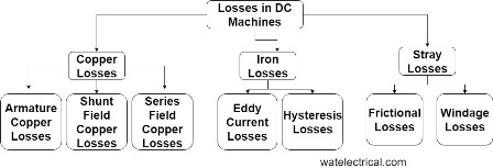
Losses in DC Machine
Applications
- These are used in various applications like lathe machines, fans, blowers, air compressors, electric traction, cranes, elevators, and vacuum cleaners.
This article discusses an overview of a DC machine. It is a device that is used for either the conversion of ME to EE or EE to ME depending upon its construction and operation. It acts as a generator when the coil is rotated in the magnetic field and acts as a motor when the rotor winding is given a DC supply and placed in the magnetic field. In the above data, it also includes construction, emf equation, working losses & applications. Here is a question for you, what is the difference between a generator & a motor?