Nowadays, most of the electric utility companies distribute electricity in the form of alternating current and voltage (AC). In fact, the power lines, transformers and service lines are designed to transfer electricity in alternating current and voltage. However, in our homes, offices, where this electricity is consumed, are filled with electrical appliances and device that consume electricity in the form of direct current and voltage (DC). Therefore, this brought about the need for a middle device that helps to transform incoming power from the line to a form that can be utilized by electrical appliances in our homes and offices. The name of this device is generally called rectifier.
In this context, a rectifier is a device that converts an alternating current supplied from a service line or socket mains to direct current and voltage that can be used to power electrical appliances most especially, a semiconductor device.
RECTIFIER THEORY
There are two major theories in rectification which are used to describe the nature of the output wave. They are;
- Half-wave rectifier theory
- Full-wave rectifier theory
HALF-WAVE RECTIFIER THEORY
In half wave rectifier, if we consider a simple sinusoidal a.c voltage, either the negative half cycle or the positive half cycle of the signal is allowed to move past the rectifier circuit. Which will result in the output shown below?
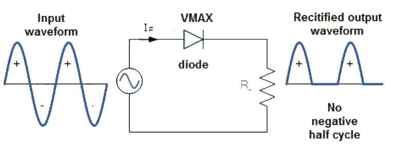
Figure 1 Half-wave rectification
FULL-WAVE RECTIFIER THEORY
In full wave rectifier, if we consider a simple sinusoidal a.c voltage, both the negative half cycle or the positive half cycle of the signal is allowed to move past the rectifier circuit with one of the halves flipped to the other halve such that we now have two positive or negatives halves following each other at the output.

Figure 2 Full-wave rectification
TYPES OF RECTIFIERS
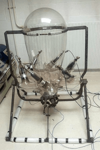
In the past, rectifiers are designed using vacuum tubes, anode plates and cathode plates but with the advent of semiconductor devices, rectifiers are designed using solid-state semiconductor components such as diodes and transistors. However, we will discuss briefly a classical rectifier, which was used before semiconductor devices became ubiquitous, it is called mercury-arc rectifier. Generally, there are seven types of rectifiers available in the market today, but we
will only discuss three of them which are used mostly in DC power supplies for our electronic systems.
Types of Rectifiers are classified as follows;
- Single(1) phase half wave rectifier
- Single(1) phase full wave rectifier
- Full wave bridge circuit
- Three(3) phase half wave rectifier
- Three(3) phase full wave rectifier
- Six wave half wave rectifier
- Three phase bridge circuit
THE MERCURY ARC RECTIFIER
This rectifier mode of operation depends on the creation of an arc between the anode and the cathode in the presence of vaporized mercury, hence the name mercury arc rectifier. The mercury atom is then ionized or split into its positive(proton) and negative(electron) component. Therefore, an anode which is positive in nature will attract the electrons, likewise, the cathode will attract the protons. Which this concept, if we want to convert sinusoidal AC to direct current, the AC voltage will be applied to the anode and cathode. The anode will conduct for the first half of the sine wave and will not conduct in the second half of the sine wave. The resulting output is shown below
SINGLE PHASE HALF WAVE RECTIFIER
The circuit for this rectifier is shown in figure 4a, with a resistive load. The a.c voltage is supplied to the diode which is connected in series with a load RL.
Working Principle:
During the positive half-cycle, the input alternating current voltage, the diode is forward biased (ON) thus, it conducts. Which makes the current to pass through it. While during the negative half cycle, the diode will be reverse biased as such, it won’t conduct, which means the negative half-cycle of the input voltage won’t pass through it. The resulting output from the diode action will result in the output voltage shown in figure 4b.
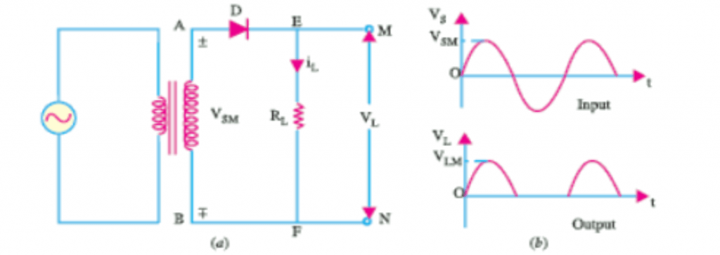
Figure 4 Single-phase half-wave rectifier
SINGLE PHASE FULL WAVE RECTIFIER
For the rectifier, two diodes work hand in hand to produce a full wave rectified input a.c voltage. Mostly, full wave rectifiers that use two diodes are always used with a center-tapped transformer. The circuit diagram is shown in figure 5a.
Working principle:
When the main supply is switched on, the ends of the transformer M and N oscillate between positive and negative half-cycle. During the positive half-cycle, the diode D1 will be forward biased which mean the positive side of the supply voltage will pass, while D2 will be reversed biased. Alternatively, during the negative half-cycle, the transformer terminal will M and N will have switched polarity making diode D2 forward biased which makes the negative
component of the supply voltage to pass through it. From the figure 5b, we can observe that the frequency of the output voltage is twice the input voltage.
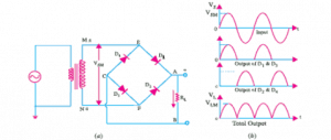
Figure 5 Single-phase full-wave rectifier
FULL-WAVE BRIDGE RECTIFIER
This standard packaged full wave rectifier is used in most DC power supplies. It consists of four diodes that switch ON or OFF depending on the current half-cycle of the supply alternating current (AC) voltage. The circuitry is shown in figure 6a. The transformer used in a full wave bridge rectifier is not center-tapped which makes more efficient than its 2-diodes counterpart. Mostly, it is found packaged in standard IC case with four terminals from figure 6c.
Please refer to this link to know more for Rectifier MCQs
Working Principle
During the positive half-cycle at the terminal, M is positive while N is negative as shown in figure 6b, Diodes D1 and D2 are forward-biased (ON) which makes current to flow through them. Whereby, diodes D3 and D4 are reverse-biased which put them in, where this electricity is consumed, OFF state. Alternatively, in the negative half-cycle, M becomes negative while N is positive, this new arrangement makes diodes D3 and D4 forward-biased which makes them to conduct and current keeps flowing through the resistance RL n the same direction in both half-cycles of the input alternating current supply.
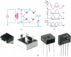
Figure 6 Full-wave bridge rectifier
APPLICATION OF RECTIFIERS
Rectifiers are applied mainly in DC power supply. Its main function in the power supply is to convert the incoming alternating current and voltage to direct current which is then filtered using a bank of capacitors and then regulated to, for example, 5V,9V, 12V and so on depending on the specification.

Figure 7 Power supply block diagram
ADVANTAGES OF RECTIFIERS
1. With the advent of low-cost semiconductors in rectifiers, DC power supply has become cheaper
2. Rectifiers will help mitigate the usage of a center-tapped transformer which means more portable packaging
3. Rectifiers are suitable for high voltage and low voltage application
4. Rectifiers have less peak inverse voltage for each diode.