Induction motor is a machine that simply operates on the induction type principle. It was invented by the scientist Tesla who earlier conducted several experiments on the working of the alternating current systems. Later, several experiments have been done to improve the performance of this type. This led to the inventions of the induction type of generator. But this type has limited access due to some of the cons than the pros of this generator. However, the motoring function finds its requirement in many areas like industries and home appliances. We shall study in detail about this type in this article like what is an Induction motor, working principle, types, advantages, and applications.
What is an Induction Motor (IM)?
Induction Motor is a singly-excited device that works on the principle of Mutual Induction. It is similar to a transformer which also works on the same principle. The difference between a transformer and IM is the transformer is a static device whereas the IM is a rotating device.
Working Principle of IM
IM works on the principle of Mutual Induction I,e whenever a current-carrying conductor is placed in a changing magnetic field an emf is induced in it. This induced emf in the primary winding (stator winding) is induced in the short-circuited secondary winding (the rotor winding) by the principle of mutual induction. The transformer also works on the same principle but with a constant frequency but IM operates with a varying frequency.
Components
IM has two main components. They are the stator and the rotor.
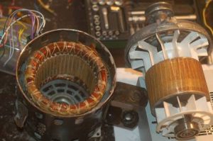
The stator is a stationary part whereas the rotor is the rotating part. The winding placed on the stator acts as the primary winding and rotor as the secondary winding. The stator and rotor of IM are shown in the figure below.
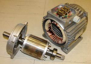
Stator and Rotor
How does an Induction Motor Start
An IM starts with the help of a rotating magnetic field that develops torque which in turn rotates the rotor of an IM.
Depending upon the supply phase system, it can be a single or three-phase IM based on the supply given.
The single-phase IM is not a self-starting motor whereas a three-phase IM is a self-starting motor. The self-starting of a motor depends upon the production of torque due to RMF.
Single-phase IM does not produce RMF as it is of single-phase so, it is not a self-starting motor. It is self-started by means of an external source. For example, a fan used for domestic purposes starts with the help of a capacitor. This is the reason why a fan stops working without using a capacitor.
Three-phase IM produces RMF which develops torque which is able to rotate the rotor so, it is a self-starting motor.
Production of RMF in a Three-Phase Induction Motor
RMF is the rotating magnetic field developed inside the IM simply it is the change of polarity between the intervals. RMF is shown in the figure below.
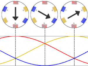
Rotating Magnetic Field
For the production of RMF, there are two main requirements they are
- The windings are to be displaced at an angle of 120 degrees shown in the figure below.
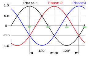

- Balanced current should flow in all three windings.
Working of Induction Motor
When a three-phase supply is given to the stator winding of the motor an RMF will be developed at synchronous speed (Ns). This developed RMF will revolve inside the air gap provided between the stator and rotor. The rotor conductors will be influenced by the RMF as whenever current-carrying conductors are in a varying magnetic field an emf will get induced. As the rotor conductors are short-circuited an emf is induced from stator to the rotor by means electromagnetic-induction. The RMF is the change of polarities with respect to the time is shown in the figure below.
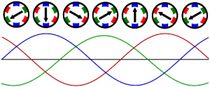
Rotating 3 phase magnetic field
The developed RMF produces a unidirectional torque which helps the rotor to rotate in the same direction as of RMF. The electromagnetic field induced in rotor conductors tries to catch the speed of RMF I,e (Ns). But it can never be able to catch its speed because due to Lenz’s law. According to Lenz’s law, it opposes the cause that produced it. So, the rotor rotates at a speed less than (Ns) which is also known as an asynchronous motor.
Induction Motor Classification
Based on the construction of rotor IM is further classified as
- Squirrel-cage IM, and
- Slip Ring IM.
Squirrel Cage Type
Construction
It consists of the yoke, wound stator, squirrel cage rotor, shaft, bearings, endrings, and a fan. The yoke is the outer part of the motor which is used as a protecting cover. The stator is the stationary part of the motor on which armature winding is wound and given a three-phase supply. The laminated sheet of a squirrel cage motor is shown in the figure below.
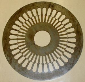
Motor Lamination
The rotor bars are laminated by the cylindrical core to reduce the eddy current losses. Squirrel cage rotor is shown in the figure below.
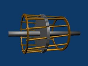
Squirrel Cage Rotor
The front portion of the motor is covered by a brush and bearing assemblies. Bearings are used to reduce friction between the moving parts. The shaft is used as a mechanical output from the motor. Endrings are provided to short the winding of secondary. A fan is provided to cool the heat generated inside the motor which is escaped out through a ventilating duct. The entire portion of the rotor looks like a squirrel cage hence, the name is squirrel cage motor.
Working
When a three-phase supply is given to the stator of IM, the armature winding develops RMF in the air gap inside the motor. This RMF rotates at synchronous speed and cuts the rotor conductors. The rotor conductors experience a force due to the current induced according to the Lorentz force equation. The squirrel cage motor is shown in the figure below.
Squirrel Motor
This current is induced as the rotor conductors are influenced by the RMF. The rotor tries to rotate at RMF speed but it cannot do so because of the opposition caused according to the Lenz law. The squirrel cage motor consumes high starting current(6-7 times of full load current), and low starting torque. These disadvantages are overcome by the introduction of Slip ring IM.
Slip Ring IM
To overcome the disadvantages of a squirrel-cage motor, slip rings are attached to the end of the circuit. It is used as an external circuit which has high resistance connected in series with the circuit. The external circuit of the slip ring IM is shown in the figure below.
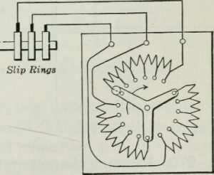
Slip Rings
Because of this high resistance high starting current is limited as the high resistance opposes the current intake. It also provides a good starting torque to the motor. After the smooth run of the motor, the external circuit is removed to avoid running losses. So, it acts as an external circuit to maintain high starting torque and consumes low current while starting. Apart from this, all the working conditions of slip ring IM is the same as that of a squirrel type.
Advantages of IM
- Low cost
- Highly reliable
- Less maintenance
- Rugged construction.
Applications
- Used for domestic purposes.
- Used in Industries.
Advantages of Slip Ring IM over Squirrel Cage
- Slip ring has high starting torque
- It consumes less starting current.
Disadvantages of Slip Ring IM
- High capital requirement
- Operational losses
- Design is complex
- High Maintenance cost.
Please refer to this link for Induction Motor MCQs, Linear Induction Motor MCQs, Mutual Induction MCQs.
Thus, in this, article, we had an overview of what is an IM, how does it start, types of three IM, RMF production, squirrel and slip ring type and the basic difference between them, advantages, and disadvantages. We can conclude from this article that IM is a rotating type machine which works on the principle of electromagnetic induction. Here is a question for the readers, how can we control the speed of an IM?