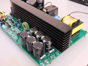
Power Supply Circuit
Electrical power supply became as a basic need in our day-to-day life, the power we are availing is 230V 50Hz AC supply. But, by using power electronics converter circuits this power can be converted into the required form and range. These converters are power electronics circuits which are further classified as step-down & step-up converters, voltage stabilizer circuit, AC to DC, DC to DC, DC to AC converter circuits and so on. Most of the microcontrollers which we frequently use in designing electronics projects require a 5V DC supply, this 5V DC can be obtained from available 230V AC supply by using AC to DC converter in the power supply circuit.
Power Supply Circuit
In general, we can observe a circuitry from which the mains power supply is taken and this circuit is used to control the power delivering to the load. Hence, this circuit can be called as a power supply circuit and there are various types of power supply circuits such as switched mode power supply, variable power supply, DC regulated power supply, etc., which are classified based on various criteria.
AC to DC Converter
There are different types of power electronics converters such as rectifier, inverter, voltage regulator, F to V converter, cycloconverter, and so on. The power electronics converter which is used for converting AC to DC is called as rectifier circuit. The maximum number of electronic circuits are using DC power for their operation and let us consider the microcontrollers (8051 microcontrollers are typically used in maximum number of microcontroller based projects or circuits) which require 5V DC regulated power supply.
There are different circuits that can be used for converting the available 230V AC power to 5V DC power using various techniques. Generally, the step-down converters can be defined as converters with output voltage less than the input voltage. Let us discuss about AC to DC converter (here considering a frequently used converter in the power supply circuit, 230V AC to 5V DC converter) and its working in detail.
4-Simple Steps to Convert AC to DC
1. Stepping down the Voltage Levels
The step-up transformers are used for stepping up the voltage levels and step-down transformers are used for stepping down the voltage levels. Thus, by using a step-down transformer the available 230V AC power supply is converted into 12V AC. The output of this step-down transformer is RMS value and its peak value can be given by the product of the square root of two and RMS value, and is approximately equal to 17V.
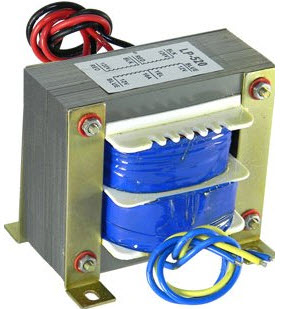
Step-down Transformer
There are two windings in the step-down transformers, primary and secondary windings in which primary winding consists of more number of turns compared to the secondary winding (less number of turns). We know that, transformer works based on the principle of Faraday’s laws of electromagnetic induction.
2. AC to DC Power Converter Circuit
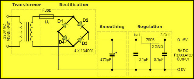
Primarily, the 230V AC power is stepped-down to 12V AC (12V RMS value of which the peak value is 17V approximately), but 5V DC is the required power. So, this stepped-down output 17V AC power has to be converted into DC power and then it is to be stepped down to 5V DC. AC to DC converter namely rectifier is used for converting the 17V AC into DC and there are different types of rectifiers, such as half-wave, full-wave, and bridge rectifiers. Bridge rectifier is mostly preferred compared to the half wave, full wave, and bridge rectifiers.
AC to DC Converter Circuit
The rectifier which consists of four diodes and are connected in the form of bridge is called as a bridge rectifier. We know that, the diode conducts only in one direction (during forward bias only), remains in off state in another direction (during reverse bias). Diode generally are uncontrolled i.e., whenever the anode voltage becomes greater than the cathode, then it starts conduction until anode voltage becomes less than the cathode. Hence, diodes are termed as uncontrolled rectifiers.
In the above circuit, during the positive half cycle of the power supply, diodes D2 & D4 conducts and during the negative half cycle of the power supply, diodes D1 & D3 conducts. Thus, the input AC power is rectified into output DC power; but DC output power consists of pulses, hence, it is termed as pulsating DC and is not pure DC. But, due to the internal resistance of the diodes a voltage drop of (2*0.7V) 1.4V occurs and thus, the peak voltage of the rectifier circuit is around 15V (17-1.4).
3. Obtaining Pure DC from Pulsating DC
The 15V DC can be regulated into 5V DC using a step-down converter, but before this, it is required to obtain pure DC power. The pure DC power can be obtained from pulsating DC using filter circuit (L-filter or C-filter or RC-coupled filter can be used to remove the ripples). The C-filter is frequently used for smoothing purposes.

Smoothing Filter to obtain Pure DC
In the circuit, a capacitor is used to store energy while the input voltage is increasing from zero to its peak value and, energy from capacitor can be discharged while the input voltage is decreasing from its peak value to zero. Thus, the pulsating DC can be converted into pure DC using this charging and discharging process of the capacitor.
4. Regulating DC Voltage
The 15V DC output voltage can be regulated using DC voltage regulators such as IC 78XX in which the last two digits XX-represents the output voltage value. Here, let us consider the IC 7805, which is used for maintaining constant 5V DC output even though the input is varying DC voltage (7.2 to 35V DC).
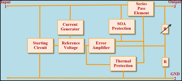
IC 78XX DC Voltage Regulator Internal Diagram
The above figure represents the block diagram of IC7805 DC voltage regulator, it consists of an operating amplifier that acts as an error amplifier, zener diode which used to provide voltage reference, as shown in the below figure.
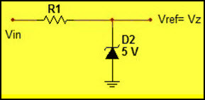
Zener Diode as Voltage Reference
The series pass element (transistor) is used to dissipate extra energy as heat and heat sink can be used for thermal protection.
know more about Single Phase AC Circuits MCQs, Voltage to Current Converter MCQs.
Do you know how to design an AC to DC converter without using transformer? Then, post your answers in the comments section below.