In the early 1870s, the electric motors used in traction did not give profitable results. But the invention of the series motor had brought much convenience in this field. Due to its performance that it can produce high starting torque. This advantage of producing high starting torque has also used the railways where the locomotives can be easily moved forward. In time, a process has also been discovered to use the technology regenerating power by the use of a series motor. In this article, we shall discuss what is a DC series motor, its definition, construction, working, circuit diagram, characteristic relationships between speed-torque and speed-current, speed control, and applications.
What is DC Series Motor?
Definition: A DC series motor is a machine that is used at a place where high torque operating conditions are required. It is a machine whose winding is associated in series with the armature winding of the motor. Due to this series arrangement, the motor is able to produce more starting torque compared to other motors.
The circuit diagram corresponding to the DC series motor, the field, and armature winding are connected in series is depicted.
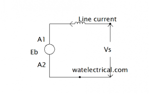
Series Motor Circuit Diagram
Where,
VT = Input Voltage
IL = Line current
IF = Field current
IA = Armature current
Rf = Field winding resistance
Ra = Armature winding
Eb = back emf
The equivalent circuit corresponding to this motor is shown in the figure below.
From the figure, we can observe that IL = If = ISe I,e as the field winding is in series the line current and series winding current remains the same.
VT = Ia (Ra + RSe) + Eb
Eb = VT – Ia (Ra + RSe)
The electrical input is given by VL. IL and the output is given as Eb .Ia
Construction & Working
The difference between this motor and the others is that the construction of this motor is slightly different from others. The motor winding arrangement is different as discussed earlier.
This motor also works on the principle of electromagnetic Induction just like other motors. The working is almost similar to a normal DC motor I,e when a current-carrying conductor is positioned under a magnetic field it experiences a force. This force is able to produce a torque which in turn rotates the rotor of the machine.
Why Series Motor is Started with No-Load
The armature current of this type of motor is decided by the amount of load applied to it. At No-load the armature current drawn by the motor is very small. But if a heavy load is applied directly during starting, the motor runs at tremendous which leads to the burning of winding.
Characteristics of DC Series Motor
From the performance characteristics of a machine, one can decide where it can be used. Let us discuss in detail regarding the characteristics by comparing its speed-torque, speed-armature current, and Torque-armature current relationships.
The voltage equation of a DC series motor is given by Eb = V – Ia Ra The speed and back Emf is given by N ∝ Eb/ɸ
The torque and armature current characteristics
The torque and armature current characteristics are explained by the equation
T ∝ ɸ . Ia
T ∝ Ia . Ia
T ∝ (Ia)2
The figure that depicts the Torque-armature current graph is shown below.
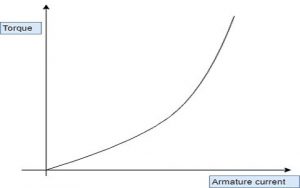
torque vs armature current
Speed armature current characteristics
The back emf equation is given by Eb = N ɸ P Z / 60 A
N ∝ Eb/ɸ
N ∝ 1/Ia
N ∝ VT – Ia (Ra + RSe)
The speed armature current relationship graph is shown in the figure below.
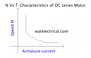
speed vs armature current characteristics
Torque-speed Characteristics
Torque and armature current relationship is given by T ∝ (Ia)2
N ∝ Eb/ɸ
ɸ α Ia
Ia = √T
N ∝ 1/ √T
The graph that shows the performance characteristics is shown in the figure below.
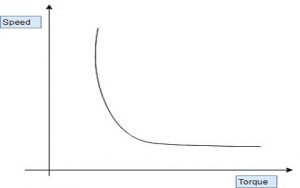
speed vs torque
Speed control of DC series Motor
The speed of this type of motor is controlled by the following methods
- Armature resistance control
- Field control
- Tapped Field control
Armature Resistance Control Method
The circuit diagram that refers to the armature resistance control is shown in the figure below.
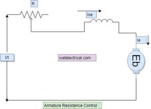
armature resistance control
From the diagram, it is clear that as and when the resistance is adjusted the speed is varied. We know that in a series motor the field winding is in series and line and field current are the same. Due to this, the current flow depends upon the value of resistance. If more resistance is put in series with the armature, then the current flow will be less and vice-versa if less resistance is put in series.
The relationship between the speed and the back emf is given by N ∝ Eb/ɸ
As speed is inversely proportional to the field current when the field current has increased the speed and vice-versa if it is decreased.
Field Control Method
The circuit diagram that explains the field control method is shown in the figure below.
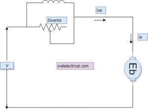
tapped diverter method
From the diagram, we can observe that a field diverter is connected across the field winding which is in series with the armature. The use of this diverter is to bypass the amount of flow armature current through the machine. As and when the armature current is varied we can able to vary the speed of the motor just like in armature resistance control. But the difference is, here we bypass the armature current by allowing some amount of current through the field winding as required. This is achieved by varying the resistance connected across field winding. If the diverter has maximum resistance, the current flows through the field winding and vice-versa if less resistance is connected.
Tapped Field Control Method
The circuit diagram that explains the Tapped field control method is shown in the figure below.
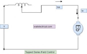
tapped field control
From the diagram, we can observe that a tapped series field resistance is connected in series with the armature. Just like the armature resistance control method, the series field is tapped at different points to vary the speed.
Thus, in this article, we had discussed what is a DC series motor. It is a motor whose field winding is combined in sequence amidst the armature winding and it produces high starting torque. We considered its construction, working, circuit diagram, characteristic relationships between speed-torque and speed-current, speed control, and applications. Here is a question for the readers, how load test is done on the DC series motor?