Modern machinery has an important role in the usage of an electric motor. Because every machine requires the operation of a motor. Most of the equipment in today’s life has the usage of a motor. An Electric motor is a machine that converts electrical energy into mechanical energy. The electric motors are classified into two types like AC motor as well as the DC motor. It uses a battery to operate, it carries the unidirectional current from the battery and operates to convert the EE to ME. This article gives brief information about the motor, its construction, working principle, different types, speed control & applications.
What is DC Motor?
A motor that is used for converting the energy from mechanical to electrical. It operates by using the DC supply.
Construction of DC Motor
The assembled parts of this motor include Frame or Yoke, armature core, commutator, brush, bearings, fan, armature winding, and shaft.
The Frame is used to give mechanical support to all the parts to be housed. It is also used as a protection device for the inner parts against environmental hazards. The motor parts which are assembled are illustrated in the following figure.
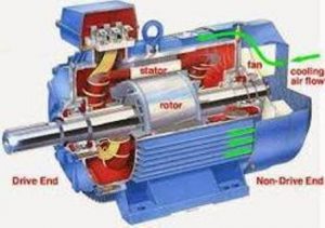
Parts of the machine
The armature core consists of armature winding, commutator, and brushes. The core is formed by the collection of steel laminated sheets. These sheets are laminated to reduce eddy current losses. The laminations are housed together to form a core. The armature consists of slots on which armature winding is enclosed. The armature winding is connected to the commutator segments and then to the brush.
The commutator segments are connected to the armature winding used for the collection of current from it. It is also used for the conversion of the current direction. The commutator segments are insulated with mica in order to avoid circulating currents with the shaft.
The brushes are made up of either graphite/carbon depending on the size of the motor. The brushes are used to get the flow of current from the commutator.
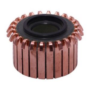
commutator
Bearings are used for the smoother operation of the rotor. A fan is used for cooling the inner peripherals of the motor. It removes the excess heat that is generated in the motor. A shaft is used to deliver the output as mechanical energy. The whole armature is assembled on the shaft.
It has its armature winding wound on the armature core while the field winding is wound on the stator. The rotating part within the machine is ‘armature’ and the stator is the stationary part of the machine.
The small motor uses permanent magnets whereas in the case of large type electromagnets are used. Permanent magnets lose their magnetism during the wear and tear. The electromagnets are those which get energize when current is passed through the winding mounted on the core.
Working Principle
The DC motor working principle is the Lorentz force equation. It states that whenever a conductor that carries current is placed in a magnetic field, it experiences a force. It also works on faraday’s law of electromagnetic induction principle. Because an electromagnetic force is induced in the coil when this coil is rotated in the magnetic field.
A DC supply is given to the armature winding such that the winding carries current. Due to the current in the winding, the coil is exerted by some force. This force is based on the Lorentz force equation, as the current-carrying coil is under the influence of the magnetic field.
The machine typical working is shown in the below diagram.
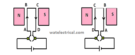
Working
The coil in the figure is marked on one side as AB and the other side as the CD. The current within the AB side is inside whereas the current within the CD side is outside. As this coil is under the magnetic lines of forces, it experiences some force. This force direction is found by using Fleming’s Left-hand rule.
Fleming’s Left-hand rule states that the three fingers forefinger, middle finger, and the thumb are pointed perpendicularly. The thumb shows the force direction, forefinger gives the field direction and the middle finger should be pointed along the current direction. The below image explains Fleming’s Left-hand rule.
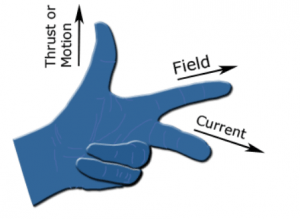
Fleming Left Hand Rule
By applying fleming left hand-rule in the coil side AB we can observe that the force is acting upwards and in the side CD it is acting downwards. So, it creates a motion for the coil to rotate in the clockwise direction. Now, as the coil rotates, the coil changes its side I,e the side AB is under N pole influence and the side CD is under the S pole influence. Now the current in coil side AB is outwards and in coil side CD it is outwards. But, the force acts in the clockwise direction. This is achieved by using the commutator segments. Without commutator segments there would unidirectional current in the coil of the motor net force acting would be zero and no torque would be developed.
The below diagram is Force acting as the coil is perpendicular to the magnetic field. At this position, the force in the coil side AB will act downwards.
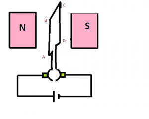
Working
As the coil is rotated the coil side also changes their positions which are shown in the figure below. At this position, the force exerted on the coil side AB is upwards.
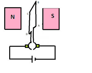
Working
So, we can understand that when the coil is parallel to the field the net force will be opposite to that of the position of the coil when it is perpendicular. To avoid this, multiple coils are used such that a unidirectional torque is developed which allows the rotor to rotate continuously.
Please refer to this link to know more about DC Motor MCQs
Different Types
These machines are classified based on the excitation and the placement of winding. They are Separately excited and self-excited motors.
Based on the winding placement classified as follows
- Series Motor
- Shunt Motor
- Compound Motor
The motors classification is shown in the following block diagram.
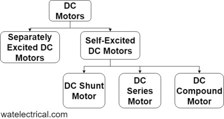
Types of the machine
Separately Excited DC Motors :
It requires a DC supply for its operation. DC supply is given to the rotor winding to exert a force on the conductors and a DC supply is also given to the stator winding to energize the field winding. So, it requires two separate DC sources for performing the operation. This process is known as separate excitation. But, these motors are not used mostly.
Self-Excited Motor :
The self-excited motor requires only one DC source which is used for both the stator as well as the rotor winding. These are the motors that are most commonly used for their advantage.
DC Series Motor :
In the DC series motor, the field winding can be connected in series with the armature winding. The resistance of the field winding is kept low such that high current flows through the winding. For this purpose, the stator winding is wound thicker with less number of turns. It produces high starting torque and decreases gradually.
DC Shunt Motor :
In the DC shunt motor, the field winding can be connected in parallel with the armature winding. For this purpose, the stator winding is wound thinner with more number of turns. It produces low starting torque and maintains constant speed characteristics.
DC Compound Motor :
In the DC compound motor, the field winding can be connected in series along with the armature winding and also in parallel with the armature winding. This motor uses the advantages of both the series as well as the shunt motor. For this purpose, the stator winding is wound thicker with less number of turns and also wound thinner with more number of turns.
The figure shows the DC shunt, series & compound motor are illustrated in the following image.
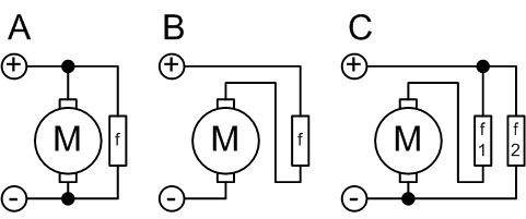
Shunt Series Compound
Speed Control of DC Motors
Speed control of these DC motors is achieved by the following methods.
By varying the armature resistance, flux, and terminal voltage.
The speed of these motors is denoted as
N = (Vt – IaRa)/Ф
- By decreasing the terminal voltage, the overall speed of the motor can be decreased.
- By increasing the flux, speed can be controlled, and
- By increasing the resistance of armature also, we can decrease the speed of the motor.
The detailed information of the speed control of DC motors is explained in the next article.
Applications
- Used in shavers, fans, blowers.
Know more about Radiation Hazards MCQs.
Therefore, in the above article, we have discussed an overview of a motor, which changes the form of energy like i/p mechanical energy to electrical energy with an input DC supply. And also discussed its construction, working principle, different types, speed control, its applications, advantages & disadvantages. Here is a question for you, what are the pros and cons of DC motors?
Leave a Reply