Well, We all know that the prominent usage of an amplifier is to amplify the signal strength whether the signal may be amplitude, frequency or other. So, the initial device which came into evolution to amplify the signal was the triode vacuum tube in the year 1906. The enhancements in digital electronics from the 20th century onwards offered modern approaches that are being added to the conventional amplifiers through digital switching so that amplification can be done easily. Moving in this scenario, the one unique kind of amplifier which we are going to have our discussion today is “Cascode Amplifier”. So, let’s dive into this concept.
What is a Cascode Amplifier?
Definition: A cascode amplifier is defined as the double stage circuit having a buffer amplifier that follows a transconductance amplifier. The name cathode was derived from the word “cathode”. Initially, cascode term implies two triodes which are a substitution for pentode, then after gradually cascode means to the two-stage amplifier. When compared with a single-stage amplifier, double-stage has more benefits in the aspects of gain, impedance, output isolation, slew rate, and others. Mostly, this amplifier is constructed either through BJT or FET.
In the two-stages, one is used for CS/CE mode and the other for CB/CE mode. The unique feature in the cascode amplifier is its enhanced input-output isolation because there is no straight coupling from the output section to input. This procedure obstructs the happening of the Miller effect and elimination of this enhances the level of bandwidth. This is the basic cascode amplifier theory.
Cascode Amplifier Circuit
Let’s discuss the cascode circuit operated through a field-effect transistor. In this circuit, the input phase is a FET CS amplifier and for the gate terminal of the transistor, Vin voltage is applied. Whereas, the output phase is the FET CG amplifier which is powered up by the input phase. For the output phase, Rd is termed as the drain resistance and from Q2, output voltage Vout is collected. In the circuit, Q2 is grounded and because of this drain voltage in FET Q1 and source voltage in FET Q2 are maintained at constant levels. This implies that FET Q2 provides minimal input resistance for the FET Q1. Low input resistance for Q1 decrease values of gain and Miller effect, and indirectly results in the enhancement of bandwidth level.
The decrement in FET Q1 gain will not impose any effect on the entire gain of the circuit as FET Q2 counteracts this. Miller effect has no impact on FET Q2 for the reason that discharge and charges from drain terminal to source stray capacitance is performed through the Rd and even the frequency response and load values are disturbed only for increased frequency ranges. In the circuit design of the cascode amplifier, output values are completely separated from the input. At source and drain terminals, Q1 has fixed voltage levels whereas at gate and source terminals Q2 has fixed voltage levels. The circuit diagram of FET operated cascode amplifier is shown as below:
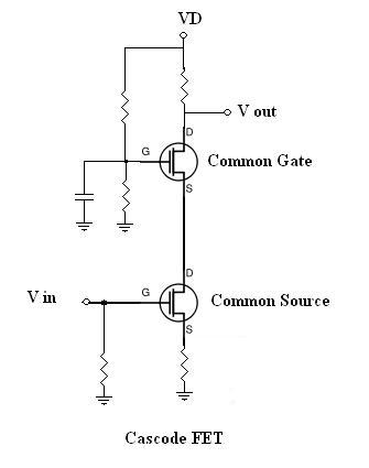
Cascode Amplifier Circuit
Folded Cascode Amplifier
This is the single-stage amplifier where it is designed in the way that common source transistor has a cas0ded connection with that of CB transistor of the reverse polarity. In this circuit implementation, a variable pair is utilized as the input section which operates as a CS stage for the cascode. The two transistor drains are connected to reverse polarity CG transistors. Then the CG transistors are linked to the dynamic current source and this ends the construction of the circuit.
With the constructional design of this amplifier, one can accomplish gain increment in the multi-stage amplifier. The circuit size can be minimal by the way of folding the cascode through reverse polarity transistors without compromising on the circuit performance, but with minimal supply voltage. With the cascode transistors, the circuits’ output resistance value can be increased that enhances the amplifier signal gain. This is the main added advantage of the folded cascode amplifier.
Frequency Response
In the cascode amplifier frequency response, the output responses are reversed in correspondence with the input. With the implementation of either cascode or common-emitter amplifiers, they deliver increased amplitude outputs. When compared with a CE signal, the cascode amplifier signal is larger and thrice more than the anticipated range. The below figure shows the frequency response of a cascode amplifier.
Stability
In the cascode amplifier, the other prominent feature that has to be discussed is its stability. The cascode constructional design itself is a stable arrangement. At the source and drain terminals, the lower transistor has almost fixed voltage level and basically there is not anything to create gate feedback. Whereas, the upper transistor also maintains a fixed voltage level at the source and gate terminals. So, there are only output and input nodes having corresponding voltage levels.
Advantages
Below are the cascode amplifier advantages:
- Cascode circuit offers increased gain, stability, enhanced impedance levels, more bandwidth levels, and slew rate.
- The construction of the circuit is so simple
- Cascode amplifier is implemented as a multiplying mixer in the superheterodyne receivers. For the upper gate, the mixer is fed with the oscillator signal, and the lower gate s fed by RF signal. Then both these signals are multiplied and the IF is considered as the upper drain of the mixer-amplifier.
FAQs
1). What is the difference between cascode and cascade?
In the cascade condition, the amplifier loads are in the horizontal configuration, whereas in cascode the loads are in a vertical configuration.
2). What is the need for a cascading amplifier?
Mostly, cascading amplifiers are employed for signal amplification purposes.
3). What do you mean by amplifier?
It is the electronic device that enhances the strength of either power, current or voltage.
4). What do you mean by cascading?
Cascading corresponds that the output of one stage is connected as an input to the next stage.
5). What do you mean by feedback in an amplifier?
Feedback signifies to the process of feeding output energy to the input is called Feedback. Feedback in the devices helps to lessen noise disturbances and provides more stability.
Reducing the Miller effect and showing many advantages, a cascode amplifier is implemented in many of the modern circuits and various industries. With the enhancement of integrated circuits and technology improvements, cascode amplifiers gain more prominence and even as a modulator, amplification devices and, others. The other device from this classification is a bimos cascode amplifier. The other question that arises in this concept is what is biasing condition in cascode amplifier?