In the modern era, the need for electrical power has increased at an enormous pace. To fulfill the required demand, huge power is needed to be delivered; hence bigger generating stations are to be designed. The electrical power generating stations may be generating electrical energy from water, atomic, thermal, or renewable sources solely contingent on the accessibility of resources and areas where these power stations are built. The areas where power stations are built might not be nearby load centers where the load is consuming power. Therefore transmitting generated power to the load center is of great importance.
There is a need for larger high voltage transmission networks for the purpose of transmission. Usually, power is generated in lower voltage levels and is economical for its transmission in high voltages. However, the distribution of electrical power is achieved in lower voltages pertinent to consumer requirements. Therefore, for maintenance of such voltage levels and deliverance of stability numerous switching stations and transformation stations are created amid consumer ends and electrical power generating stations. The transformation and switching station is generally known as a substation which is further elaborated below.
Substation Definition:
The electrical substation can be defined as a network of electrical components comprising of power transformers, busbars, auxiliaries, and switchgear etc. The components are interconnected such that creating a sequence of a circuit capable to be switched OFF while running on normal operation through manual commands while in emergency situations it can be switched OFF automatically. The emergency situations may be an earthquake, floods, or short circuit etc.
The electrical substation does not have a single circuit but is composed of numerous outgoing and incoming circuits which are connected to a busbar i.e. common entity among circuits. The substation receives electrical energy directly from generating stations through incoming power supply lines while it delivers electricity to the consumers through outgoing transmission lines. A substation which is near to the electrical power generation is also known as grid substation.
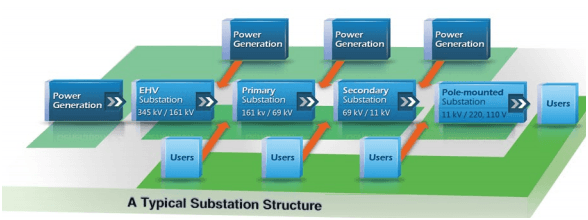
Substation Structure
Major Tasks of Substations
There are numerous tasks associated with power substations in the distribution and transmission system. Some of the major tasks that substations perform are as follows.
- It serves as protection hub of the transmission system.
- It maintains the frequency of system confined in targeted limits and has to deal with load shedding.
- It controls the exchange of electrical energy amid consumers and generating stations.
- It is ensuring transient stability along with steady-state stability of the system.
- It delivers sufficient line capacity hence securing supply.
- It helps in reducing the flow of reactive power, hence gaining voltage control.
- Through line carrier, it performs data transmission to ensure monitoring of network, protection, and control.
- It helps in fault analysis and pinning cause for a failure, hence improving the performance of the electrical network.
- It ensures reliable supply through feeding network at numerous points.
- It assists in determining energy transfer with help of transmission lines.
Single Line Diagram of an Electrical Substation
The single line diagram of the 33kv substation is depicted in the figure below. The connection of the substation is divided as
- Incoming or power feeder connection (33kv Incoming Line)
- Power transformer connection via Lighting Arrestor & Busbar
- Voltage transformer connection for control and metering.
- Outgoing feeder for feeding the other subsequent substations or switchgear.
- Circuit Breaker & Isolator between the incoming and the outgoing lines.
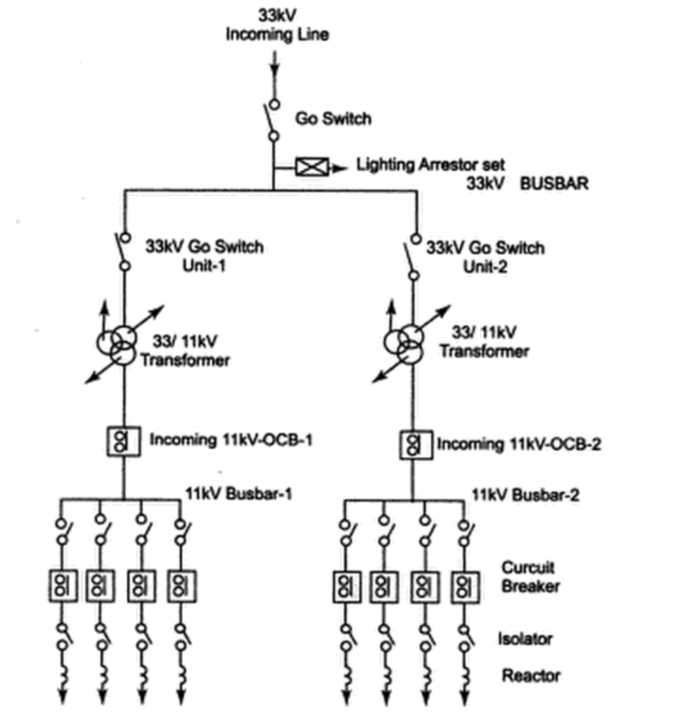
Single Line Diagram of Substation
On the incoming 33kv incoming feeder line side, the transformer is connected to the bus bar and the lightning or surge arresters are connected as a phase to the ground as the initial connection equipment. A circuit breaker is connected between the 11kv bus-bar and each incoming and outgoing circuit with the support of the isolator being provided on each side of the circuit breaker.
Different Substation Layouts
The following are the general substation layout diagram. These are also referred to as substation design.
1) Single Busbar Substation
This design is simplest and has an ease of operation and maintenance. This design has a minimum reliance over signaling for the necessary protection of its operation. Furthermore, there is a facility for supporting economical operations of feeder bays. Following is a general schematic diagram of single busbar substation.
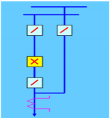
The characteristics of single busbar substation are as follows.
- There is a circuit breaker for protection of each circuit, hence there is no loss of supply in outages.
- In case of fault on the transformer of a feeder, circuit breaker results in loss of feeder or transformer circuit which is restored after isolation of faulty circuit breaker.
- Loss of circuit is involved in the maintenance of the circuit breaker of the transformer of the feeder.
- There are bypass isolators amid circuit isolator and busbar hence allowing maintenance of circuit breaker without any loss to the circuit.
- Any fault in busbar is causing loss of a transformer or feeder. Hence, maintenance of a busbar will result in an outage of 2 circuits.
2) Mesh Busbar Substation
The mesh busbar substation is a complex design and has few technicalities involved in its operation and maintenance. The generic schematic diagram of mesh busbar substation is as follows.
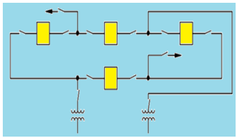
The following are characteristics of mesh busbar substations.
- There is a requirement of two circuit breakers for disconnecting or connecting of a circuit and disconnection is also requiring opening up of mesh.
- There is an option of maintenance of circuit breakers without loss of supply.
- One circuit breaker loss occurs when busbar is faulty while fault in breaker involves loss of two circuits.
3) One and Half Circuit Breaker Substation
The one and a half circuit breaker layout of a substation are not common because of its high cost and complex technicalities involved in its operation and maintenance. The generic schematic diagram of the mentioned substation is given below.
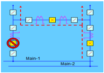
The following are characteristics of one and half circuit breaker layout.
- High security is involved alongside the loss of supply.
- There is a possibility of operating only one pair of circuits, a pair of circuits, or groups of circuits.
- The circuit breakers are having a complex arrangement and higher costs are involved.
So to conclude, Electrical Substations are of great importance in today’s Power Transmission and distribution industry. For more information regarding the various types of substations and components of substations, you can refer to our other articles.
Know more about Mesh Analysis.
Please refer and know more about Oil Circuit Breaker MCQs.
Image Credits :
Single Line Diagram of Substation (Electrical Pw Dist Sys By Kamaraju)
Substation Layout – Mohit Kumar Singh et.al, International Research Journal of Engineering and Technology (IRJET)