In the analysis of various circuits, we all know that their analysis involves huge calculations and various equations, and other tools. Whereas in the case of complicated circuits, the analysis is not easy and using a simple analytical approach like series and parallel is not accurate. It needs multiple equations to solve and various techniques. So, the basic methodologies are improvised to Mesh Analysis that results in reducing the complexity of analyzing the circuit and helps in finding out the variable values in the circuit. So, this article helps in understanding Mesh analysis, what is a branch, how to implement this procedure, and other examples.
What is Mesh Analysis?
Mesh analysis is also termed as Mesh Current method which is a procedure useful in solving currents and voltages for planar circuits at any of the locations in the electrical circuits. Mesh is considered as a loop where it does not have other loops inside it. This technique considers mesh currents as variables other than considering currents in the elements. Because of this, mesh analysis does not require multiple equations to analyze the circuit.
This analysis procedure uses the KVL principle to know the value of unknown currents. When mesh currents are known, then voltages can be easily found out through Ohm’s law.
So, now a branch is considered as the path that creates a connection between two nodes so that a branch includes a circuit element. When a mesh has only one branch, then it can be considered as Ib = Im.
Where ‘Ib’ represents branch current and ‘Im’ represents mesh current
Step by Step Procedure of Solving an Electrical Circuit
This section explains the step-by-step procedure of mesh analysis in solving electrical circuits.
- Find the number of meshes in the circuit and label all the meshes either clockwise/anti-clockwise path
- Find the elements in the circuit and observe what is the amount of current that flows across each element in the form of mesh currents
- For all the meshes, write mesh equations. The mesh equations can b written using Kirchhoff’s voltage and Ohm’s law
- So, to find the mesh currents, solve all the mesh equations.
- Through this procedure, initially mesh currents can be known, and then voltages across every element in the circuit can be found.
Mesh Current Method with Example
The below mesh current diagram consists of two meshes and it is a planar circuit that has 4 resistors. The first mesh and RA and RC resistors whereas the second mesh have RB, RC, and RD resistors. For each mesh, the amount of current flow differs, and it is easily evaluated through mesh equations. And the voltage source is considered as V1.
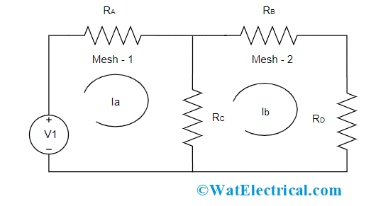
Basic Mesh Circuit Diagram
In the case of the first mesh, the voltage source and the resistors are in series connection so both the resistors have the same current value and the circulating current is denoted Ia. And in the case of the second mesh, the three resistors have the same amount of current value and here in this loop, the current is denoted as Ib. Here, is the unique case where RC resistor is shared between both the meshes which correspond that two various current values flow across RC. So, the current flow across Rc is given by Ia – Ib.
For 1st mesh,
When KVL law is applied for the first mesh, the voltage is considered as the difference between Ra and Rc resistors. So, as per Ohm’s law
Va = Ia * Ra
Vc = (Ia – Ib) * Rc
And Voltage V1 = (Ia * Ra) + ((Ia – Ib) * Rc)
For 2nd mesh,
There is no voltage source for 2nd mesh. So, based on the KVL principle, in a closed-loop series connection circuit, the potential difference of all the resistors in the loop is considered as ‘0’. Then the equation is given by
((Ia – Ib) * Rc) + IbRb + IbRd = 0
So, by solving the 1st and 2nd mesh equations, the flow of current in both the meshes can be known which means Ia nd Ib values are known.
Example of Mesh Analysis
Below is the circuit that is used for solving two meshes using mesh analysis. Here, the circuit consists of two voltage sources named V1 and V2 and there are two meshes.
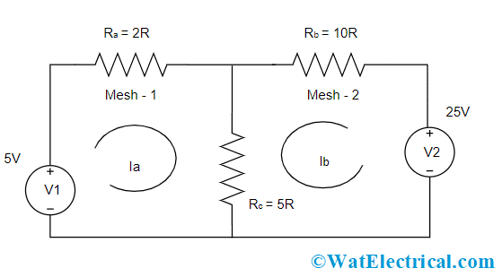
Mesh Analysis Example
For 1st mesh
The voltage source and the resistors Ra and Rb are in series connection so both the resistors have the same current value and in the circulating current is denoted Ia. As per Ohm’s law, the voltage in each component is given by
V1 = 10V
VRa = Ia * 2 = 2Ia
For the Rc resistor, there are two loop currents as it is the shared resistor between two meshes. As each mesh has different voltage sources, the current flow across Rc is given by ia + Ib
VRc = (Ia + Ib) * 5 = 5 (Ia + Ib)
As per the KVL principle,
V1 = 2Ia + 5 (Ia + Ib)
5 = 2Ia + 5 (Ia + Ib)
5 = 7Ia+ 5Ib
For 2nd mesh
The three resistors has same amount of current value and here in this loop, the current is denoted as Ib. So, the voltage across each component in the mesh is given by
V1 = 25V
VRb = Ib * 10 = 10Ib
VRc = (Ia + Ib) * 5 = 5 (Ia + Ib)
Based on KVL principle,
V2 = 10Ib + 5 (Ia + Ib)
25 = 5Ia + 15Ib
Ia + 3Ib = 5
So, from two meshes, – we have the equations
5 = 7Ia+ 5Ib
Ia + 3Ib = 5
By solving both the above equations, we get
Ia = 0.625 Amps
Ib = 1.87 Amps
Mesh Analysis with Independent Voltage Sources
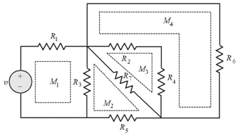
In order to understand this concept, let us remember that a closed-loop is drawn at a node and then proceed with path tracing so that we will be back to the actual node by passing through intermediate nodes only once. A mesh is considered as the loop which should not have any other loops. The below circuit shows four meshes and those are named Ma, Mb, Mc, and Md. Here, mesh currents all the meshes are considered to flow in a clockwise direction. As per the above picture with four loops, the outer loop should not be selected as it has one more loop inside it.
First, let us consider two meshes as shown in the below picture.
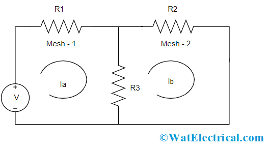
Two Mesh Circuit
Consider the mesh currents as Ia and Ib and implement the KVL principle in each mesh. As the current flow is in a clockwise direction, sum all the voltage drops and rises in both the meshes. Assume that voltage drop is considered as +ve and voltage rise is considered as -ve. So,
Mesh 1 = v – IaR1 + (Ia – Ib)R3 = 0
Mesh 2 = (Ia – Ib) R3+ IbR2 = 0
And in the case of the R3 resistor, the voltage is taken as (Ia – Ib) * R3. Here Ib is considered as negative because we are considering the current flow clockwise. When both the equations are solved, Ia and Ib values are known and then branch currents can also be measured using mesh currents. Through the evaluation of branch and mesh currents, branch voltages can be known. Suppose if we have 5 meshes with 5 mesh currents, then 5 independent mesh equations are obtained. This set of 5 equations are independent.
Mesh Analysis with Independent Current Sources
Consider the below circuit having an independent current source. Here Ib is considered as null, so only Ia has to be determined.
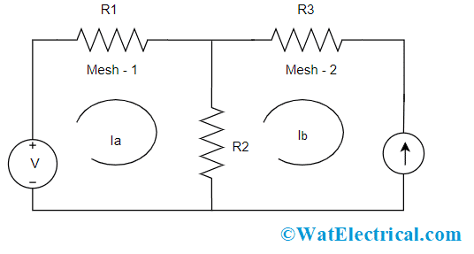
Independent Current Sources
For 1st mesh, when KVL law is applied, we get
(R1 + R2) Ia – R2Ib = v
As Ib is null, we have
(R1 + R2) Ia – R2 = v
So, Ia = (v – R2)/(R1 + R2)
In a similar way, when a current source which is common for both the meshes is considered, we get
Ia = (v – (R2 + R3)/(R1 + R2 + R3)
So, independent current sources can be managed by writing the relationship between current sources and mesh currents and these equations are called as constraint equations.
What is Super Mesh Analysis?
Super mesh analysis is the advanced procedure of implementing mesh analysis for the analysis of highly complicated circuits. Here, two meshes share a similar current source as a common component. In this procedure, the current source lies inside the super mesh so that for each mesh only one mesh can be obtained other than having multiple meshes.
One mesh can be ignored when the current source position is on the circuit’s parameter. On the other hand, the KVL principle is implemented only for the meshes/super meshes in the revamped circuit.
Example of Super Mesh Analysis
Consider the below circuit and the aim is to find the values of V3 and Ia, Ib, and Ic.
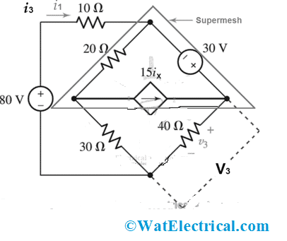
Super Mesh Analysis
Solution:
For 1st mesh
- 10 Ia + 20 (Ia – Ib) + 30 (Ia – Ic) = 80
- 10Ia + 20Ia – 20Ib + 30Ia – 30Ic = 80
- 60Ia -20Ib – 30Ic = 80
Now, use Kirchhoff’s voltage law for super mesh, where super mesh is the combination of mesh 2 and mesh 3. Then
- 30 = 40Ic + 30 (Ic – Ia) + 20 (Ib – Ia)
- 30 = 40Ic + 30Ic – 30Ia + 20Ib – 20Ia
- 70Ic – 50Ia + 20Ib = 30
So, we have two equations. But the aim is to find the value of three variables Ia, Ib, and Ic. So, three equations are needed. For that, an independent current source in the super mesh is related to the considered mesh currents. Then
15Ix = Ic – Ib
Ic = 15Ix + Ib
So, after solving three equations, we get
Ia = 0.58 Amps
Ib = -6.15 Amps
Ic = 2.6 Amps
And to find V3, we use Ohms law
V3 = Ic * R3
Substituting the values,
V3 = 2.6 Amps * 40
V3 = 104 Volts
Disadvantages
This section explains the disadvantages of mesh analysis.
- Mesh analysis is applicable only for planar circuits or else this approach is not useful
- When the network is large, it will have more meshes and also the number of equations gets increases. This becomes complex in solving the values of circuit elements
1). What is the difference between loop and mesh?
Both loops and meshes are considered as part of the electrical circuit. Loop is the closed path in the circuit where no node rather than once comes across. In the circuit, a mesh is also a closed-loop where no other paths are present it.
2). What are the limitations of mesh analysis?
- Mesh analysis is suitable only for planar circuits.
- Does this technique impose complexity for solving highly complicated circuits?
3). Which Kirchhoff’s law is used in mesh analysis?
Kirchhoff’s voltage law (KVL) is used in mesh analysis which is used to know the values of unknown currents.
4). What is a dependent source?
A dependent source can be a voltage/current source where its value is based on the voltage/current anywhere in the circuit.
5). What is the difference between mesh and nodal analysis?
Nodal analysis is used to know nodal voltage values using KCL law, whereas mesh analysis is used to know mesh currents using KVL law.
6). What is Mesh Matrix?
After finding the equations for the meshes in the circuit using mesh analysis all the values that are in the equations are represented in a matrix form for easy analysis and this is called a mesh matrix.
7). What are the basic principles applicable to mesh and node analysis?
For mesh analysis:
- When the branch is correspondent to one mesh, then mesh current = branch current
- When the branch is shared by two meshes, then the branch current is either sum or difference of two mesh currents.
For Node analysis:
Node analysis equations are considered at every node mentioning that branch currents specific to that node must be summed to ‘0’
8). Why do we use mesh analysis?
It is used to know the currents and also voltages in an indirect way for electric circuits.
know more about Kirchhoff’s Law MCQs.
Please refer to this link to know more about Biot Savart Law.
So, in the conclusion of super mesh analysis, this is an important technique in analyzing electric circuits. And this article has provided complete information on mesh analysis procedures with solved examples, super mesh analysis, drawbacks, and uses too. Also, know what are the dependent sources in super mesh analysis?
