A function generator is one of the most useful devices in the electronic domain. In modern-day, electrical terminology, troubleshooting is the most important concept and the under analysis needs multiple controllable signals to simulate the normal functionality. This requirement is easily resolved by a function generator where they can provide various kinds of signals.
The first function generator was designed by Robert Brunner where is a minimal frequency device and aimed fundamentally at geographical analysis, servo testing, and vibration observations. Today, this article is going to explain function generators working, circuitry, types, and their benefits.
What is Function Generator?
A function generator is generally termed as a signal generator that gives multiple kinds of output waveforms (sine, square, sawtooth, and others) based on the input signal. The device also provides the option of adjusting frequency ranges between a few Hz to some 100KHz. This instrument is considered as so versatile because it provides various types of waveforms with different frequency ranges. The other feature of a function generator is its ability to offer variation in the shape of the wave, magnitude, offset, and frequency whereas a load is necessary before doing the adjustment.
In addition to adjusting the waveform characteristics, the device also adds an offset DC to the signal. In general, function generators function at minimal frequency levels whereas expensive models might function at high-frequency ranges.
Also, phase locking is another feature provided by the instrument which corresponds that one function generator is employed for phase locking the other function generator and the resultant signals can be adjusted in phase by a variable amount. Apart from phase locking, one function generator can also be phase-locked to the harmonics of other function generators. By varying the amplitude and phase of the harmonics, any kind of signal might be generated by the addition of the base frequency of one device with the resultant harmonic of other devices.
Block Diagram & Its Working
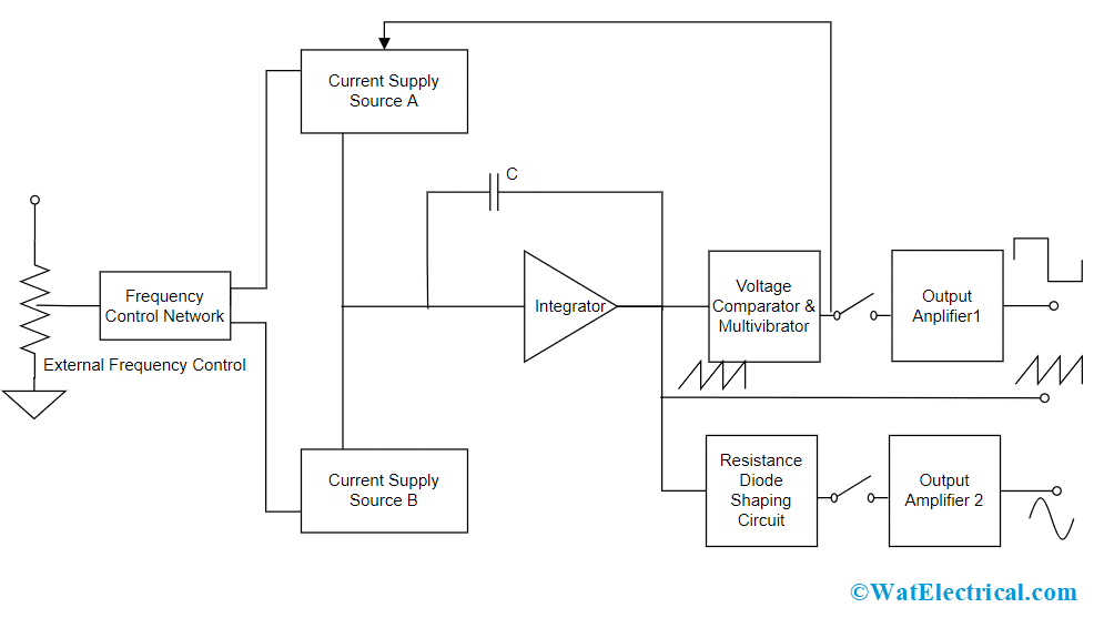
This section explains the block diagram of the function generator along with its working. Below is the block diagram picture:

Block Diagram
For a function generator construction, a frequency controlling network is used where is frequency is regulated by the change in the current’s magnitude level. An integrator is used where this is driven by two current sources represented as current source ‘A’ and current source ‘B’ and both these current sources are controlled by the frequency regulated voltage.
A constant current is provided to the integrator section using current source ‘A’ and because of this integrator’s voltage level increases in proportion with time. The below equation determines the linear increase in the output signal voltage.
Vout = [-1/C] ʃt0 i dt
Ang change in the current level either increasing or decreasing correspondingly changes the output voltage slope and thus regulates the frequency level.
Also, in the function generator block diagram, a voltage comparator, and multi-vibrator device is used where this triggers a change in the phase of the output voltage at the integrator at the previously defined peak level. As because of the change in phase, the current supply from source ‘A’ stops and source ‘B’ starts to supply power to the integrator. Because the source ‘B’ providing power, the integrator generates a reverse current. This reverse current results in a drop in the output of the integrator proportionally with time. Before this time, when the output reaches the maximum level, the comparator again alters its state and gets back to the current source ‘A’.
Therefore, the integrator output is a triangular waveform where its frequency is based on the current supply of both the current sources. And the comparator output is a square waveform. The circuit also has a resistance diode network that modifies the triangular wave slope having a minimum distortion of nearly 1%. And the amplifier at the output stage assists in providing two waveforms, thus the resultant signal is observed using an oscilloscope.

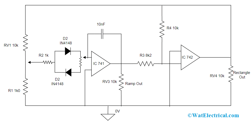
Function Generator Circuit
This is the function generator working explaining with the block diagram.
Abilities of Function Generator
As discussed, function generators hold the capability of generating multiple waveforms, and those are explained as below:
Pulse Waveform – The pulse waveform is similar to the square waveform, but it has a space ratio of 1:1. This wave is generally used for digital kind of applications.
Triangular Waveform – This signal proportionally moves in between low and high levels. This output is produced by an operational amplifier performing as an integrator. The output from a triangular wave generator can also be a square wave and this is employed as a fundamental for the generation of other kinds of waveforms. This is also utilized in testing amplifiers because the levels of clipping and distortion can be clearly noticed in a triangular wave when compared with a sine waveform.
Sawtooth Waveform – This is also considered as a type of triangular wave, but the variation is it has sharper rising edges than that falling edges, and this makes the waveform shape to be a sawtooth. The same triangular wave generator can be used for the production of the sawtooth waveform, but the only difference is different falling and rising times formed by varying the rate of charge for rising and fall elements.
Controlling Aspects of Function Generator
Apart from providing the selection of fundamental waves, a function generator can even provide multiple controlling options and those are discussed below:
- DC offset value – This helps in varying the signal voltage corresponding to ground level.
- Frequency – The frequency control in the function generator varies the basic frequency level where the wave repeats, and this is not dependent on the type of waveform.
- Duty cycle – This controlling option alters the high and low voltage ratio timings in the sine wave which means altering the square wave having a 1:1 duty cycle to another type of waveforms such as triangles having the same level of rising and fall timings.
- Selection of waveform – This controlling option allows to a selection of various types of fundamental waveforms which are sine, triangular and square waveforms.
- Triggering input – This is the input terminal used for counting the frequency
- Adjustment knob – This control sets the parameter chosen by other buttons in the device
- Adjustment for amplitude-offset – This is the knob that helps in adjusting either the DC offset voltage or amplitude level of the signal
- And these are the fundamental controlling options available in a function generator.
Specifications
This section explains the technical specifications for a general type of function generator.
| Parameter | Value |
| Output amplitude | Generates peak to peak voltage of 10 volts |
| DC offset voltage | Generates an adjustable voltage of -5 volts to +5 volts |
| Output impedance | 50 Ohms |
| Frequency stability | 0.1%/hour for the analog type of function generators 500 ppm for the digital type of function generators |
| Maximum distortion for sine waveform | 1% for analog type devices, For arbitrary wave generators, it is < -55dB below 50kHz and -40dB above 50 kHz |
| Supported modulation types | Amplitude, Phase, and frequency modulations are supported |
| Frequency range | Multiple levels of frequencies are generated |
Types
As the progress of technology moving forward, there are various types of function generator which suits even for the current digital technology and the types are as follows:
Rack-based type – This is like a component present inside the rack system such as PXI. This main usage of this type of function generator is testing the applications and it has a slot that is used either for controlling or linking to the computer. Cards used for testing the instrument are placed into the slot thus making the test system to be ready for testing any specific application.
The testing cards can be of any kind of testing devices like oscilloscope, voltmeter, ammeter, and others.
Computer-based type – This is a distinct process where it uses a software-dependent computer to offer the necessary waveform types and then employs digital cards of the computer audio for the wave. Even this approach is not expensive, it may not hold the ability for delivering high accuracy when compared with other types of function generators.
And if there is any damage in the output because of misconnections or testing results, this leads to high expensive repairs.
USB type – Many various small types of function generators can be used as USB type of function generators. This device has a core section of the function generator inside the section which connects the computer through a USB device. This procedure explains that the power and controlling interfaces can utilize computers other than costly ones and the space necessary to offer these inside a huge box for testing the device.
Benchtop type – This is the extensively used type of function generator. The testing components are present in the box which is placed in the lab workbench. The testing equipment is controls, power supply, a connector to connect the output and display.
And these are the main function generator types.
Applications of Function Generator
There are extensive uses of a function generator across multiple domains and those are:
In semiconductor domain
- Used for testing DC power supply
- For testing the delay margin
- Analyze the audio DAC
- To test clock frequency functional range of digital circuits
In medical domain
- Used for testing medical ultrasound devices, pacemakers, implantable medical equipment, and other detector circuits
- In radiofrequency domain
- Function generators are used for calculating the BPF frequency response
- Used in EMC radio observations
- Utilized in operational testing of RFID receiver integrated circuits
- Measures pulsed noise figures
In automotive domain
- Employed for testing and optimization of engine controlling units
- Analyze switching signals of IGBT circuitry
In addition to these, function generators are also extensively used in industrial applications, research, and many others. So, this article has completely explained function generator working, specifications, types, circuit diagram, and its applications. Know, how a function generator is used in ICL 8083?