A regulator is a device that maintains constant and regulated power at the output terminals across the load. Due to voltage fluctuations, and load unbalancing, it becomes very important to maintain a constant voltage at the load side. The voltage fluctuations affect the function of the device, and hence the circuit. If the system consists of sensitive loads such as electronic devices, it becomes very important to maintain load voltage constant. Power quality is also an issue while handling the sensitive loads, as unwanted harmonics damage the load and cause undesirable losses. The regulator maintains the load voltage constant and free from harmonics. They are further classified based on configuration and application. In advanced regulators other current-controlled components like MOSFET, IGBT can also be used instead of a transistor. This article discusses an overview of the transistor series voltage regulator and its working.
What is a Transistor Series Voltage Regulator?
A transistor series voltage regulator can be defined as a device that keeps the output voltage at a constant level. As shown in the figure, the transistor series voltage regulator acts as the regulating element. It takes the unregulated input and provides the regulated output.
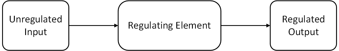
Block Diagram
Embedded in an Integrated Circuit(IC) chip, it maintains the load voltage constant for any variation in the input voltage. It works along with the transistor principle which modifies its resistance with a change in bias voltage. It uses a Zener diode to maintain the base voltage of the transistor constant. It is frequently used in electronic circuits like voltage regulators, adapters, rectifier circuits, etc. to provide a regulated output voltage. The regulator is connected in series and shunt with the load based upon application.
Transistor Series Voltage Regulator Working
As shown in the figure, a transistor series voltage regulator consists of the following components.
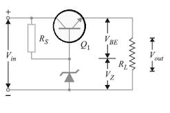
Circuit Diagram
Transistor (Q1) – It helps to modify the resistance of the circuit to maintain voltage constant. Its terminals are Base, emitter and collector. The Zener diode is connected to the base of the transistor, and input is given at the collector side. The load is connected to the emitter. Let VBE be the base-emitter voltage.
Zener Diode – The Zener diode as shown in the circuit diagram, is connected to the base of the transistor. The Zener diode is used to set the fixed reference voltage to the transistor base. The voltage across Zener diode Vz always remains constant irrespective of change in input voltage.
Series Resistance Rs – Series resistance RS is used to limit the current through Zener diode.
Load Resistance RL – It is the resistance of the load connected at the output terminals.
Working
- Assume that the input voltage given at the terminals is 12 V. Which is the unregulated DC supply voltage given at the input terminals. Assume that the breakdown voltage of the Zener diode is 9 V. This means that, Zener diode starts conducting at 9V. Since the Zener diode is connected to the base of the transistor, 9 V becomes the reference voltage to the transistor base, which is a fixed value.
- The voltage across the load, i.e. the output voltage is the voltage difference between Zener diode voltage and the voltage across base-emitter. That is it can be given as
V0 = VZ – VBE - The voltage across base-emitter is conducting voltage of the transistor whose value is 0.7V. As the input voltage is 12 V, hence the output voltage becomes 9 – 0.7 = 8.3 V as per the above equation.
- Now if there is an increase in input voltage, let us say 12.5 V, then the voltage across the load also increases initially. It increases to 8.7 V. But the Zener diode maintains the voltage constant at 9 V.
- Therefore the voltage of the transistor becomes less than 0.7 V. For this to happen the resistance across collector-emitter increases. (This is the property of transistor, transfer resistance). Hence now the output voltage maintains constant at 8.3 V.
- Now let us consider the case for a decrease in input voltage. A decrease in input voltage will decrease the load voltage initially. But again the load voltage has to be maintained constant. This time, the resistance across collector-emitter decreases, which increases the base-emitter voltage. It can be noted that the transistor collector-emitter
- Resistance changes as per the change in input voltage. This happens due to the transistor principle and fixed voltage provided by the Zener diode.
- In both the cases with a change in input voltage, the load voltage remains constant. Hence it can be seen that with a change in input voltage, the output voltage remains constant. That is how a transistor series voltage regulator acts as a regulating element
Transistor Series Voltage Regulator Experiment
In this experiment, the properties of the regulator element are verified. In this experiment, an unregulated DC supply is given to the circuit. And based on Zener diode voltage, the output across the load is verified. An increase and decrease in input voltage are done and the constant output voltage is verified. Further, the regulating element is verified by combining it with a rectifier. This means that AC input is given to the rectifier, which converts the AC to pulsed DC based on the rectifier principle. The pulsed DC is again fed to transistor series voltage regulator and a constant DC output voltage is observed.
Classification of Voltage Regulators
Based on the manner in which the transistor is connected to load, the voltage regulators are classified as
- Series Voltage Regulator – In this circuit, the transistor is connected in series with the load
- Shunt Voltage Regulator – In this circuit, the transistor is connected in parallel with the load
Similarly based on variations in the circuit, they are further classified as
- Line Regulator – In this circuit, variations in the line are being regulated by the circuits. Variations in the line indicate variations in supply voltage. Variations in supply voltage may be caused due to minor faults, or harmonic interpretations.
- Load Regulator – In this circuit, variations in the load are being regulated by the circuit. The change in load may be caused due to changes in circuit constants, or abrupt addition or deletion of load demand
Advantages and Disadvantages of Voltage Regulator
The advantages are
- The regulated output voltage is obtained from this circuit.
- Low noise, less ripple, and stable performance are obtained.
- Components required to build the circuit are easily available.
- It does not have any electromagnetic interference.
- Response time is fast for any line or load changes
The disadvantages are
- The efficiency of the circuit is less
- Since a lot of dissipated, heat sinks are required.
- In the voltage regulators, the output voltage is always less than the input voltage.
Please refer to this link to know more about FET MCQs and Transistors MCQs
FAQs
1). Can a transistor be used as a voltage regulator?
Yes, a transistor along with a Zener diode connected to its base acts as a voltage regulator.
2). How does a shunt voltage regulator work?
In shunt voltage regulator, the transistor is connected in parallel to the load, Along with Zener diode, it provides regulated output voltage by transistor principle.
3). Which type of regulator is more efficient?
As compared to the series and shunt voltage regulators, the series voltage regulator is more efficient. In general switching voltage regulators are considered as most efficient voltage regulators
4). Where is the voltage regulator located?
A voltage regulator is located between line and load.
5). What is the purpose of the voltage regulator?
The voltage regulator is used to providing a regulated voltage at the load end. Irrespective of load changes, or changes in line, the output voltage remains constant.
Hence we have seen the operating principle of transistor series voltage regulator, its applications along with advantages and disadvantages. This circuit is one of the most widely used integrated circuits in the field of electrical and electronics engineering. With the advent of power electronics devices, the transistor has been replaced with power electronic devices along with advanced modulating techniques to maintain the output voltage constant. Here is a question for you, why do transistors are called as current-controlled devices?