In the scope of electrical technology, a parallel circuit is described to be shunt. Direct current motors and generators where the armature and field windings are parallelly connected are termed as DC shunt motors and DC shunt generators. Fundamentally, a similar machine can be utilized as motors and generators. The foremost variation in between these devices is that in the DC shunt motor the input is of electrical energy and the output is mechanical energy whereas it is vice-versa in the DC shunt generator.
General Overview of DC Shunt Motor & DC Shunt Generator
The general overview of these motors is discussed below.
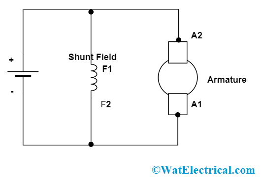
DC Shunt Motor
The DC shunt motor is also termed as Shunt wound DC motor and it comes under the classification of self-excited DC motor where the armature winding and field windings are in parallel connection. As there is a parallel connection between the windings, they are subjected to a similar supply voltage.
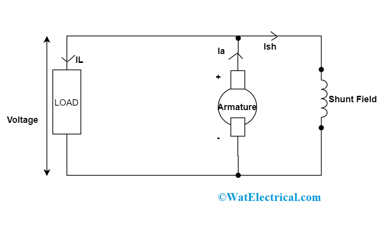
DC Shunt Generator
This comes under the classification of a self-excited DC generator where the armature winding and field windings are in parallel connection. There will be minimal current across field winding because it is wounded with slender wire and has a greater number of turns.
EMF Equations
When a certain voltage is applied to the DC shunt motor, the armature collects the necessary amount of current required to develop a potent magnetic field where this will get related to the magnetic field developed by the shunt windings and this causes rotation of the armature. This armature rotation generates back EMF and this resists the armature voltage and lessens the armature current. When the load across the motor gets increased, then the rotation of the armature will be slowed down and also back EMF will be decreased as EMF is linear to speed.
DC Shunt Motor
Eb = (Ф.P.Z.N)/60
Where ‘Eb’ corresponds to back EMF
‘Ф’ corresponds to magnetic flux
‘P and Z’ is the number of poles and coils
‘N’ is the speed of rotation
When Eb voltage is reduced and with a linear supply voltage level, then the net voltage will get increased. So,
Enet = E – Eb
When Enet is increased, then the armature current value also will be increased. As torque value is linear to that of armature current, torque value also enhances.
T = (Ф.P.Iarm.Z)/2.∏.A
Where ‘T’ is the torque developed and ‘A’ is the cross-sectional area
In the end, the developed torque permits the motor to enhance the speed of rotation and balance at the time of loading.
2. In the DC shunt generator, armature current is represented as:
DC Shunt Generator
Iarm = Ifield + ILine
And the EMF equation is given as
E = (Ф.P.Z.N)/60A
Where ‘E’ corresponds developed EMF
‘Ф’ is the magnetic flux
‘P and Z’ are number of poles and coils
‘N’ is the speed of rotation in rpm
‘A’ corresponds to the number of parallel paths
and Iarm, Ifield, ILine are armature, field, and line currents.
ILine = Ishunt = V/Rshunt
The induced EMF is:
E = V + IarmRarm = V+ (Ishunt + ILine) Rarm
Comparisons between DC Shunt Motor & DC Shunt Generator
Feature | DC Motor | DC Generator |
| Input and Output | Here, the input is DC current and output is mechanical energy | Here, the input is mechanical energy and output is DC current |
| EMF | Coil uses EMF and used for axle rotation | The EMF generated across the coil is transferred to the load |
| Types | Compound wound and Shunt | Series wound, compound, and Shunt |
| Rule of operation | Operation is dependent on Fleming’s left-hand concept | Operation is dependent on Fleming’s right-hand concept |
| Back EMF | Eb = V – IarmRarm | Eb = V + IarmRarm |
| Effect of commutation | For modifying the polarity of the magnetic field, commutators are utilized in motors | For canceling the polarity effect, generators are utilized in motors |
| The relation between EMF and the terminal voltage | Armature EMF is less than that of terminal voltage (Eb < V) | Generated EMF is more than that of terminal voltage (Eb > V) |
Please refer to this link to know more about DC Generator MCQs, Linear Induction Motor MCQs.
FAQs
1). Where shunt motors are used?
These are utilized when linear speed is necessary and when starting circumstances are not difficult.
2). What are the applications of DC shunt generator?
These are used for lighting, charging of the battery, portable generators, and many others.
3). What are the applications of DC shunt motor?
These are used in conveyors, dynamic braking, reversing applications, and in many of the industrial purposes.
4). What is the difference between shunt and series motor?
Shunt motors have parallel winding and have minimal current values whereas series motors have series winding and so field current and armature currents are similar.
So, this article shows a basic overview and the differences that exist between DC shunt motor & DC shunt generator. Also, know more about the concepts like how the working of the shunt generator and shunt motor varies and their related concepts?