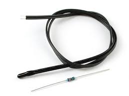
A thermistor is a temperature sensor constructed of semiconductor material that exhibits a large modification in resistance in proportion to a tiny low modification in temperature. Thermistors are inexpensive, rugged, reliable and responds quickly. Because of these qualities thermistors are used to measure simple temperature measurements, but not for high temperatures. Thermistor is easy to use, cheap, durable and respond predictably to a change in temperature. Thermistors are mostly used in digital thermometers and home appliances such as refrigerators, ovens, and so on. Stability, sensitivity and time constant are the final properties of thermistors that create these thermistors sturdy, portable, cost-efficient, sensitive and best to measure single-point temperature. Thermistors are available in different shapes like rod, disc, bead, washer, etc. This article gives an overview of the thermistor working principle and applications.
What is Thermistor and How it Works?
A thermistor is an inexpensive and easily obtainable temperature sensitive resistor, thermistor working principle is, it’s resistance depends upon the temperature. When temperature changes, the resistance of the thermistor changes in a predictable way. The benefits of using a thermistor is accuracy and stability.
Types of Thermistors
Thermistors are classified into two types such as
- Thermistor Elements
- Thermistor Probes
Thermistor Elements
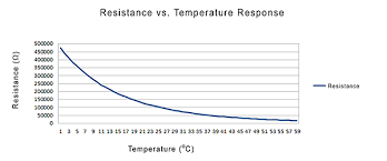
Thermistor elements are the simplest form of thermistor, it is commonly used when space is very limited. OMEGA offers a wide variety of thermistor elements which vary not only in form factor, but also in their resistance Vs temperature characteristics. Since thermistors are non-linear, the device used to read the temperature must linearize the reading.
Thermistor Probes
The standalone thermistor element is comparatively delicate and cannot be located in a rugged environment. OMEGA offers thermistor probes that are thermistor elements fixed in metal tubes. Thermistor probes are much more suitable for industrial environments than thermistor elements.
Simple Fire Alarm Circuit Diagram Using Thermistor
This simple fire alarm circuit is based on the thermistor and fire detection is possible through this circuit.
- This circuit is very useful in home security systems.
- This circuit works based on the principle of switching property of the transistor
- The thermistor and resistor R1 forms potential divider n/w to drive the transistor
- The semiconductor materials used for thermistors are sensitive to temperature
- The transistor is switched ON by the voltage drop through the resistor R1.
- Consider the atmosphere’s temperature is around 25°C, and then the resistance of the thermistor changes, then the voltage across the thermistor changes according to the principle of ohm’s law V=IR.
- When the voltage across resistor R1 is low, then it is not sufficient to turn ON the transistor.
- When the temperature increases, the resistance of thermistor decreases, so that the drop across the resistor R1 increases which turns ON the transistor.
- When the transistor is turned ON, the current from Vcc starts to flow via 6V buzzer which generates a beep sound. The diode is used for enabling unidirectional conduction and the capacitor removes sudden transients from the thermistor.
The temperature of the thermistor can be calculated from the measured resistance by using the Steinhardt-Hart equation.
1/T=A+B*ln(R)+C*(ln(R))3
Where, R in W and T in oK
In the above equation, A, B, and C are the constants, that can be determined from experimental measurements of resistance. For a typical thermistor, here are some data points

Using these three values we can get three equations in A, B and C.
(1/273) = A + B ln(16330) + C (ln(16330))3
(1/298) = A + B ln(5000) + C (ln(5000))3
(1/323) = A + B ln(1801) + C (ln(1801))3
These equations can be solved and calculated for A, B, C
A = 0.001284
B = 2.364x 10⁻⁴
C = 9.304x 10⁻⁸
Using these values you can calculate the temperature and the reciprocal and we get a plot of resistance vs Kelvin

Plot of Resistance vs Kelvin
Calculating the Temperature from Resistance
If you have resistance value, then you can solve for the temperature by from the above Steinhardt-Hart equation.
1/T=A+B*ln(R)+C*(ln(R))3
From the above equation, we can calculate the temperature
T=1/[A+B*ln(R)+C*(ln(R))3]
Testing of a Thermistor
This is just a sample test for a thermistor. The multimeter has to be kept in the mode of resistance. The two terminals of the multimeter are to be connected to the two terminals of the thermistor.

Testing of a Thermistor
We need not to focus on polarity here. Now, heat the thermistor by moving the heated soldering iron tip to it. Now you can observe the changes in the multimeter readings smoothly depending on whether the thermistor under test is PTC or NTC.
For faulty thermistors, the following things should observe.
- The change in the readings of thermistor will never be smooth
- For a short thermistor, the meter reading will be always zero, whereas in an open thermistor the meter reading will be always infinity.
Applications of thermistors
- A Thermistor is used to measure the temperature.
- The thermistor is used as an electrical circuit component
- For temperature compensation
- Circuit protection
- Voltage regulation
- Time delay, and Volume control.
- Thermistors are used in an automotive applications
- Instrumentation and Communication
- Consumer electronics
- Food handling and processing
- Industrial electronics
- Medical electronics
- Military and aerospace
For better understanding of this concept, here we have explained two projects as an application.
Temperature Controlled Load by Thermistor Sensor
The main aim of this project is to design a circuit to control a load automatically using a thermistor sensor with a fixed temperature limit. When the temperature increases beyond an exact limit, a lamp is switched ON to bring the temperature to a normal value. Due to the automatic switch On of the load, this system doesn’t require human interference for observance the load of the temperature
A negative co-efficient thermistor is employed with an op-amp to activate the relay within the event of the temperature going out of range. Thermistor is usually used instead of different temperature sensors because they are cost effective.
But most of their resistance vs temperature characteristics are extremely nonlinear and need correction for applications that need a linear response. A change in temperature will change the input parameters to the op-amp. The op-amp delivers an o/p to energize the relay and switch ON/OFF the lamp through its contacts.
In future, this project can be developed by using a digital temperature sensor instead of an analog one. By doing so, we can increase the accuracy of the temperature control system.
Industrial Temperature Controller
The main intention of this industrial temperature controller project is used to control the temperature of any device in industries. The temperature can be displayed on the LCD display in the range of –55°C to +125°C. The 8051 microcntroller is a heart of the circuit, which controls all the functions. As a temperature sensor DS1621 IC is used. This IC provides 9-bit temperature readings, these readings specifies the control of the temperature of the device. User defined temperature settings are stored in an EPROM memory through the microcontroller.
Max and min temperature settings are entered to the microcontroller through a set of switches which are stored in the EEPROM -24C02.Maximum and minimum setting are meant for allowing any hysteresis necessary. Set button is used first and then the temperature setting by INC and then the enter button.
Similarly, for the DEC button. A relay is driven from the microcontroller through a transistor driver. The contact of the relay is used for the load (lamp) in the circuit. For high power heater load a contact may be used, the coil of which is operated by the relay contacts in place of the lamp as shown.
Thus, This is all about thermistor, thermistor working principle, its types and its applications, these are used for various temperature sensing applications. Hope that the thermistor characteristics and applications, in addition to this, might have given you a better & a wholesome understanding of the topic. Please write your suggestions and comments in the comment section given below. Here is a question for you, why is a potential divider circuit needed for thermistors?