The variable resistor is an element that offers variable resistance to the circuit. By adjusting its internal configuration, we can obtain variable resistance at the load side. This element is frequently used in electrical and electronic circuits to vary the current flowing in the circuit. Apart from varying current, this element is also used to control some basic parameters like speed, temperature for commonly used electrical loads. A simple example would be, the speed control of single phase induction motor (ceiling fan) through a potentiometer (variable resistor).
Variable Resistor Definition
Its an element, which offers variation in load current or voltage due to change in its internal resistance. The method by which internal resistance is varied depends on the type of variable resistor. The symbol for a variable resistor is shown below.
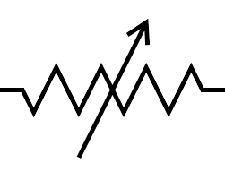
Variable Resistor Symbol
In the figure above, the symbolic representation of the variable resistor is shown. The arrow implies the value of the resistance can be varied. As we discussed before, the method by which the value of resistance is varied depends on its classification. Let us see the type of variable resistor.
Working Principle of Variable Resistor
To understand the working principle, it must be noted that we are discussing the case where terminal C is variable. As can be seen from the circuit equivalent, the terminal C position can be varied by moving the sliding contact. It must be remembered that the resistance of an element is a function of length, cross-sectional area, and resistivity of the material. By varying any of these, the resistance of the element varies. Now in this circuit, as the position of the terminal C is varied, the effective length of the wire or conductor varies. Hence in between the terminals B and C, we are obtaining a variable resistance.
As the resistance is varied, the current in the load varies as per Ohms Law. Hence by varying the position of the sliding contact, a change in current or voltage across the load can be obtained. It must be noted that the terminals shown in the figure can be interchangeable. They are not fixed.
Types of the Variable Resistor
The different types of variable resistors include the following.
Potentiometer
This is one of the most common variable resistor used. In this type, based on the position, the voltage is varied. Hence the name is given as a potential-meter or potentiometer. Also called a rotary rheostat. It has got three terminals as shown in the figure below.
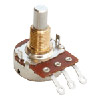
Potentiometer
Out of the three terminals, two are used. One is connected to the resistive element, and the other is connected to the knob. As seen in the above figure, by rotating the knob above, the position of the resistance differs. We know that resistance depends on the area of cross-section, length, and specific resistance. So by varying the position of the knob, the length varies and hence resistance varies. This change in the resistance cause change in voltage, and hence the potential difference. A simple example of this potentiometer is changed in the speed of the ac motor by applying a varied armature voltage. They are also frequently used as power control devices. They can control voltage, current. Light intensity, sound, etc. Also used in heaters, oven, electric motors, and many other electrical appliances.
Rheostat
This is also called a linear rheostat. In this type, the resistance is adjusted by varying the position of the wiper shown on the horizontal bar. The wiper is in connection with the resistance material below. This element has two ends for obtaining variable resistance. As the wiper is moved from one end to another, a variable resistance is obtained. This type is often used in laboratories. The wiper is placed atop an insulated ceramic core. And a long wire is wounded around the core. They are also called as wire wound resistors. Due to the nature of the movement of the wiper, they are also called slide rheostats.
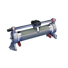
Rheostat
As compared to potentiometers, rheostats carry more current. In other words, the current rating of rheostats is very high. It may range up to 10 A. The high rating is because of the wire. Since the current-carrying capability depends on the cross-sectional area of the conductor, to carry high currents, the thick wire is used to wound around.
Please refer to this link to know more Resistors MCQs
Digital Resistors
A digital resistor is the same as a potentiometer. It may be also termed as a digital potentiometer. But here, there is no physical knob to obtain a variation in the resistance. Instead of using any mechanical knob, it uses digital signals for varying the resistance. In the circuit below is shown a digital resistor ladder.
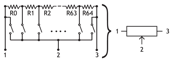
Digital Resistor Ladder
In this figure shown above is a digital resistor ladder. As it can be seen that, a number of resistors have been connected in the circuit. By closing the switches, we can obtain a series connection of resistor shown. The number of connections, also called steps decides the output resistance of the circuit. To adjust the number of ladder connections, an onboard chip is placed on the resistor. Also called as a wiper. Digital resistors, also called digital pots have a number of applications. Often used in bridge circuits like Wheatstone bridge, Andersons’s bridge, etc. which are used to calculate inductance and capacitance. The bridge circuits operate on balancing impedance principle for which, the resistance needs to be modified. The other applications are digital to analog converters, brightness control, gain control, etc.
Presets
Presets are the mini version of potentiometers. The working principle is the same as potentiometers, i.e. a small knob is available to vary the resistance. But here, we don’t have any horizontal knob projecting outside.
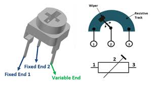
Preset
Like other variable resistors, it has also one fixed end and variable end. As shown in the figure above. The variation of the mechanical knob on the top varies the value of resistance. Such resistors are designed to be mounted directly on printed circuit boards (PCB). They are mostly used for applications that how low specifications, like setting the frequency of an alarm tone, checking the resistance of a photovoltaic cell, etc.
Variable Resistor Connection
To understand the variable resistor connection and working principle lets take the rheostat. The internal configuration of the rheostat is shown below.
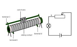
Rheostat-Working
It consists of three terminals, terminal A, B, and C. The circuit equivalent of the device is also shown. It can be seen that the load is placed between the terminals B and C. The terminal B or C can be the varying one. In between the two terminals A and B, a long wire is placed. The area of the wire is determined by the current-carrying capacity or current rating. The wire is wounded on a ceramic core. The sliding contact, or also called as wiper comes in contact with the wire.
Variable Resistor Applications
The variable resistor has a number of applications. A few of them has been listed below
- They are used to control the speed of DC motors. As they provide variable resistance, it varies the current and hence voltage. So speed can be easily controlled by the principle or armature voltage control.
- They are used in household applications like to change the speed of ceiling fans. Its nothing but a simple potentiometer.
- They are frequently used in laboratories in educational institutes and research wings for carrying out experiments.
- Other common applications of potentiometers are, controlling sound, light intensity, etc. Also used in microphones and sound systems to adjust the volume.
- Digital Rheostats have a number of applications. They are embedded as integrated circuits in a printed circuit board. They can be linked with signal processors to control resistance electronically.
- Preset rheostats have low specification applications like radio, transmitter circuits, etc.
FAQs
1). Does a variable resistor change voltage?
Actually a variable resistor does not change voltage. It changes the resistance of the element. But due to changes in resistance, the voltage also changes. It follows the Ohms Law.
2). How do you test a variable resistor?
First, the continuity in the connection of the resistor is checked. Then the working. It can easily be done using a multimeter.
3). What is the symbol of a resistor?
The resistor symbol is shown below.
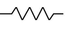
Resistor
4). What is the 10 K variable resistor?
10 K variable resistor means, its resistance can be varied up to 10 thousand ohms.
5). How many terminals a rheostat has?
A rheostat has three terminal
Hence we have seen the working principle and classification of variable resistors. They are one of the frequently used components in electrical and electronic appliances. The working principle of all types of variable resistors is the same. We are obtaining by changing the length of the coil. Now it can be thought that does a variable resistor exists which offers variable resistance due to change in temperature?