The first transmission line was demonstrated over an extended distance by physicist Stephen Gray on July 14, 1729, to show that one can transfer electricity through that method. This demonstration is used damp hemp cords which are balanced through silk threads. In 1882, electric power transmission was accomplished by the first high-voltage transmission between Munich & Miesbach. After that in 1891, the first three-phase AC overhead line construction was done on the International Electricity Exhibition occasion conducted in Frankfurt, between Lauffen & Frankfurt. After so many inventions, the highest overhead line building was commenced in the year 2003, in China. This article discusses an overview of transmission lines.
What is Transmission Line?
A transmission line can be defined as a conductor or many electrical conductors designed with a uniform cross-section along the transmission line to carry electrical signal or electricity above large distances by minimum distortion & losses. This is used to transmit electrical power from the substation to the different distribution units. Here, air performs as a dielectric or an insulating medium in between the conductors.
Generally, the transmission line is made up of ACSR conductors and the mechanical strength of this conductor can be improved by the steel. In these conductors, the majority of strands are made up of aluminum because it is a very good conductor for electricity and as compared to copper, it has less weight for each unit length.
Transmission Lines
In transmission lines, the distance is much more between the line & ground for safety purposes. For supporting the line conductors, the electrical tower is utilized which is made up of steel material to provide high power to the conductor. To transmit high voltage over long distances in the line, a high-voltage DC is used.
Parameters of Transmission Lines
The performance of transmission lines mainly depends on different parameters like resistance, capacitance, shunt conductance & inductance. All these parameters are distributed uniformly through the line which is known as the transmission line distributed parameter.
The series impedance can be formed by inductance & resistance whereas the shunt admittance can be formed by capacitance & conductance. Some of the parameters of the line are explained below.
Line Inductance
The flow of current within the transmission line can induce the magnetic flux. Once the current flow within the line alters, then magnetic flux can also be changed because e.m.f induces within the circuit. The magnitude of induced e.m.f mainly depends on the rate of flux change. In the transmission line, the produced emf will resist the current flow within the conductor, called the line inductance.
Line Capacitance
The air within the transmission line performs as a dielectric medium which comprises the capacitor in between the conductors so that it increases the line capacitance or stores the electrical energy. The capacitance of the conductor is defined as the presence of charge per unit of potential difference. The capacitance in short transmission lines is negligible whereas in long transmission, it is a very significant parameter. So it affects the voltage regulation, efficiency, system stability & power factor.
Shunt Conductance
Shunt conductance is the leakage current flow between the conductors of the transmission line. This conductance can be uniformly distributed along the entire length of the transmission line. It is represented with the symbol ‘Y’ & it is calculated in Siemens. The air in between the conductors of the transmission line acts as a dielectric medium. When the alternating voltage is applied within a conductor, current flows in the dielectric medium due to dielectric imperfections, so it is known as leakage current. This current mainly depends on the condition of the atmosphere like surface deposits & moisture.
Types of Transmission Lines
In an electric power system, transmission lines carry electric energy from one point to another. In addition, this current can be carried by either underground or overhead lines. The transmission lines operate at relatively high voltages, they transmit the power above large distances & transmit large amounts of power. These lines are available in three types overhead, sub-transmission, and underground.
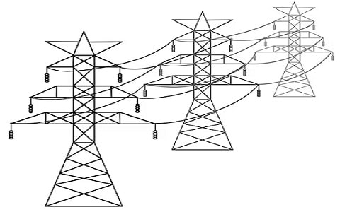
Overhead Transmission Lines
An overhead transmission line or OHTL is used within electric power transmission & distribution for transmitting electrical energy for large distances from power plants to substations & then to the user. These transmission lines carry a three-phase current that is balanced by poles/towers. An OHTL includes several components like supports, conductors, insulators, conductor fittings, spacers, overhead ground wire & brackets.
The structure of overhead transmission lines will be changed based on the regions around the world. The simple structure of OHTL has a wooden pole above one arm where the arm is used to hang the electrical wires. Other structures have tabular steel poles & concrete poles.
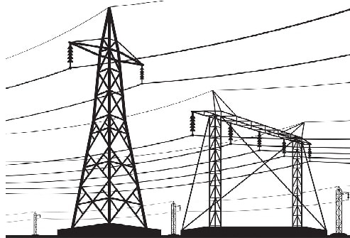
Overhead Transmission Lines
The maintenance & inspection of the overhead transmission line is very important. So making normal electrical inspections for these transmission lines will make a difference in power reliability & faults.
Subtransmission Lines
A high-voltage system that carries power from the high-voltage transmission system & reduces it to a low voltage for transmitting power to the largest industrial plants or distribution substations is known as a sub-transmission line. The sub-transmission voltage is sometimes tapped along the way to use in large commercial to industrial operations.
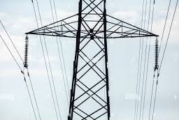
Subtransmission Type
Underground Transmission Lines
Underground transmission lines are telecommunication or electrical cables buried without protection and located in trenches, tunnels, or conduits. So these transmission lines are more common within populated areas.
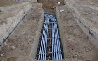
Underground Transmission Lines
Sometimes, these transmission lines are utilized as an alternative to overhead transmission lines. As compared to overhead transmission lines, these transmission lines were supported by some community rallies because overhead cables can detract from the landscape. Underground transmission lines are much larger than overhead transmission lines. They need an external safety jacket; insulation & shielding for keeping the conductor very cool.
Transmission Line Types Based on Length
Transmission line based on length is available in three types short, medium & long transmission lines which are discussed below.
Short Transmission Line
The physical length of the transmission line which has less than 80km is known as a short transmission line. The voltage range of this transmission line is below 69 kV and the capacitance effect in this transmission line will be negligible by taking inductance & resistance only in calculation.
Medium Transmission Line
A transmission line with above 80 km and below 250 km physical length is known as a medium transmission line. The operating voltage range of this line ranges from 69 kV to approximately 133 kV. The capacitance effect in this transmission line is present and distributed capacitance type can be used for calculation purposes.
Long Transmission Line
A transmission line with more than 250 km of physical length is known as a long line. The voltage range of this line is above 133 kV. The line constants of this type of transmission line like resistance, capacitance, inductance & conductance are distributed above the whole length of the line uniformly.
Efficiency
The transmission line efficiency can be defined as; it is the ratio of delivered power at the receiving end to the power transmitted from the transmitting end. Transmission efficiency can be mathematically given by the following expression:
ηT = (VRIR CosθR/ VSIS CosθS) x 100
Where,
VR, IR & CosθR are the receiving-end voltage, current & power factor whereas VS, IS & CosθS are the transmitting end voltage, current & power factor.
Characteristic Impedance
The most significant physical property of the line is the characteristic impedance (Z0). In a coaxial cable, the characteristic impedance is the inner and outer diameter’s function & the insulation’s relative permittivity between the inside and outside of conductors.
The line’s characteristic impedance is resistive purely; so no phase shift is introduced & all signal frequencies will broadcast at an equal speed. This is true theoretically simply for lossless lines which means transmission lines have zero resistance along the infinite resistance & conductors in between the conductors.
Reflections and Matching
The transmission line impedance is not proposed to limit the flow of current in the way that a normal resistor would. This is only an unavoidable effect of the interaction in between a cable including two conductors within close proximity. The characteristic impedance importance in the RF design context lies in the reality that the designer has to match impedances to avoid reflections & attain the highest power transfer.
PCB Transmission Line
A type of interconnection utilized to move signals from their transmitter to the receiver on a PCB is known as a PCB transmission line. This type of line includes two conductors like a signal trace & a return path or a ground plane. The PCB dielectric material is mainly used to make the volume between the two conductors. PCB transmission line is significant mainly because their characteristics are directly controlled by the designer. The normal PCB transmission lines are available in two types the microstrip & the stripline. PCB interconnects are normally small & they do not exhibit the behavior of transmission-line until frequencies of signal approach 1 GHz.
What are transmission lines used for?
The transmission lines are used for transmitting high-frequency signals above short or long distances with less power loss. These transmission lines connect substations & power stations in order to transmit large amounts of electricity efficiently at high voltage with no loss, so it plays a fundamental role in supplying electricity.
How long are transmission lines?
The short transmission lines are shorter than 50 km, medium transmission lines range from 50 to 150 km and long transmission lines are longer than 150 km.
What are the properties of transmission lines?
The important properties of transmission lines that determine their main performance mainly include inductance, capacitance, resistance, and conductance.
Are transmission lines AC or DC?
Transmission lines carry either AC, DC, or both combinations but the majority of transmission lines around the world carry power AC type.
Thus, this is an overview of transmission lines that are extensively used for transmitting high-frequency signals above short or long distances with less power loss. Here is a question for you, what high voltage-based transmission lines utilize?