In the concept of electrical engineering and development, a switch is a device that has the functionality of connecting and disconnecting the conduction way in the electric circuit where it obstructs the current or redirecting it from one conductor to another conductor. The general type of switch is an electromechanical component that includes either one or more sets of mutable connected to outer circuits. The first implementation of the light switch was done using quick break technology and this was proposed by John Henry Holmes in the year 1884.
The technology behind the implementation of the switch eliminated the issue of the switch’s contacts generating electric arching when the circuit was either opened or closed state. There are numerous configurations and types of switches available, and the one prominent type is a 2-way switch. So, today this article explains clearly two-way switch connections, wiring, working principle, and uses.
What is a Two Way Switch?
Two-way switch corresponds that regulating single light or electric components through the usage of two different switches located at different places. Here, every switch possesses the same terminal which is L1 and L2 and L corresponds to a line terminal. Through the electrical wire, both the switch terminals are connected. This forms a switch that performs as 2 switches that control a single application.
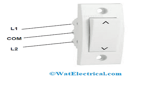
Two Way Switch with Terminals
Two Way Switch Working Principle
To be clear, let us consider a simple example that a person stays on top of the stairs and he wants to turn on the light that is above the stairs. Then using a two-way switch he can either ON or OFF the same light in two different locations. This means that he can turn on the light when he is either at the top or bottom of the stairs through a 2-way switch. In order to depict this example, below is the staircase wiring circuit diagram 2 way switch.
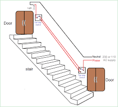
Staircase Switching Circuit
Here we need two 2-way switches. The common terminal present for one 2-way switch is connected to the phase line and the other switch common terminal is connected with the load. It is always recommended to have a switch connected with the phase line only. The way terminal in both the switches is connected together and the neutral line has a direct connection with the load which is light.
2 Way Switch Wiring
It was already discussed in the above section that a 2-way switch is very useful in many cases where this works just by toggling the switch positions. Apart from this, there are other approaches to establishing a switch connection. The oldest approach of connection is not in use these days whereas the other is in use now and it is the safest way of connecting a two-way switch. This latest way is employed in both domestic and industrial applications. The below sections describe both approaches of wiring.
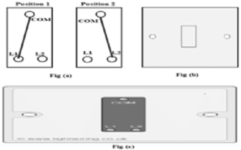
Before knowing how to connect a two-way switch, it is more crucial to know about a device called a two-way light switch which is the most required component in 2-way switching. This light device is not dependent on the type of wiring. This is the fundamental single pole switch having three terminals. These terminals are named COM, L2, and L1 whereas in few cases the terminals are called COM, 1 way, and 2 way. There are two positions in this connection wherein one position, L1 and COM are connected and in the second one, L2 and COM are connected.
This kind of connection is termed as a break before make because the first connection needs to be broken to create the second connection.
Modern Way of 2 Way Switch Connection
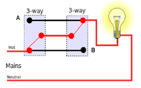
In this way of switching, it makes use of 2 light switches having 3 wire control. The below diagram is the two-way switch circuit diagram using a three-wire.
In the schematic diagram, it can be observed that the COM terminal in both switches is connected. The L1 edges in two switches will have a connection with the AC supply line whereas the L2 edges in the switches are connected to the light bulb’s one end and the other end of the light bulb is connected to the AC supply line neutral terminal. The picture shows that the light is in OFF condition when the switch is toggled, then the light will be turned ON, and toggling the switch will make the light move into ON and OFF states.
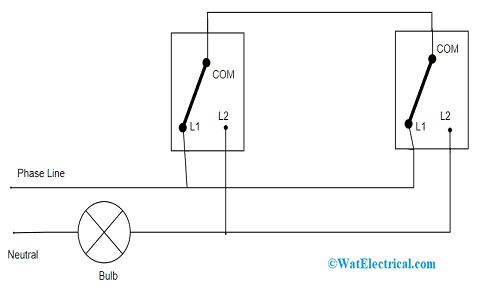
Standard 2 Way Switch Wiring
When this structure is compared with digital electronics, then the operation of the Ex-OR gate is the same, where the light’s ON and OFF states are based on the COM ends of switches that are connected to L1 and L2 edges. This approach is mainly advised when both the neutral and line wires are received from the same circuit of light even this uses additional wire.
The conditions in this method are shown below:
| Switch 1 COM | Switch 2 COM | State of Light |
| L1 | L1 | OFF |
| L1 | L2 | ON |
| L2 | L1 | ON |
| L2 | L2 | OFF |
Older Method of 2 Way Switching
This switching methodology is mainly useful for industrial and home applications which is also termed as two wire-controlled wirings. This is mainly suggested for recent day applications. Below is the picture which shows the schematic diagram of two wire-controlled 2-way switches.
Here, L1 terminals from two switches are connected together and L2 terminals from two switches are also connected together. The COM end of the first switch has a connection with the phase line and the COM end of the second switch has a connection with the light’s one terminal. The other end of the light is connected to the AC supply neutral line.
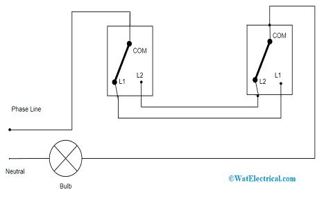
Older Method of Two Way Switch Wiring
In the default condition, the light is in an OFF state whereas when one of the switches is toggled, then the light moves to ON state. This operation is the same as the Ex-NOR gate. Though this approach does not need cables, this is not much recommended because the neutral and phase lines arrive from various lightning circuits and the other drawback is electromagnetic induction interference. As the current-carrying conductor releases electromagnetic radiations. When the neutral and phase lines are close to each other, they cancel off each other electromagnetic radiation.
The conditions in this method are shown below:
| Switch 1 COM | Switch 2 COM | State of Light |
| L1 | L1 | ON |
| L1 | L2 | OFF |
| L2 | L1 | OFF |
| L2 | L2 | ON |
One Gang Two Way Switching Method
This method of 2 way light switch consists of three terminals which are similar to the connection of a single-way switch. But here the OFF state can also be used. The labeling of the terminals will be different based on every company and those will be like C, L1, and L2 or else L1, L2, and L3.
The one gang 2-way switch is employed in the situation when two switches handle similar light like the switch controlling at top and bottom positions of the staircase. This can also be used as a one-way switch through L1 and COM terminals. The one gang two way switch diagram is shown below:
One Gang Two Way Switching
In the first position which means that switch is in the ON state, the L1 and COM terminals are connected together and in the second position (the switch is in the OFF state), the L2 and COM terminals are connected together. This switching method has no connection between L2 and L1.
Multiway Switching Method
In this methodology, there are mainly three kinds of conditions to be considered which are short circuit, closed and open circuits. When the switch is in the OFF state, then the circuit moves into OPEN condition.
Let us start this topic by considering a light switch in an electric circuit.
Multiway Switching
When there are two entrances in a room and there might be the requirement of using three-way switches due to the reason that they have three contacts. The lines that are present in between the two switches are termed travelers. With this, light can be ON or OFF through the 1st switch and similarly for the 2nd switch, or else the light can be ON through the 1st switch and OFF using the 2nd switch.
Whereas a four-way switch is generally utilized to manage light from two or more locations and this is simply considered as a cross-over switch where it has two different states. The switch is placed in between the other two switches and it will be toggled between active travelers. This signifies that any switch which has a light ON or OFF. The multiway switching circuit is shown below:
Differences between 1 Way and 2 Way Switching
A 2-way switch is more economical and also the equipment and wiring are more when compared with a one-way switch. The main use of a two-way switch is controlling a device can be done from two various locations. The naming of switches itself indicates that 1-way switch uses 1 switch and 2-way switch consists of two switches whereas the wiring is complicated in the 2-way switch.
The main variation between the two switches is that a 2-way switch ON and OFF condition is based on the ON and OFF positions of the switch that is located at another location. One-way switches are used for small spaces whereas 2-way switches are used for staircases, huge auditoriums, and other large spaces.
How a Safe 2 Way Wiring Can be Done?
A few of the precautions to be considered while making wiring connections are as follows:
- Ensure that the AC power supply is turned OFF before wiring, and either connecting or disconnecting the switch or else there might be chances of the switch getting burnt.
- Don’t start wiring when there is a power supply to the switch. This might result in an electric shock to the circuit
- Don’t allow operation of switches to be in open environment those have flammable kind of gases
Know more about Toggle Switch MCQs, Electric Circuit MCQs.
Apart from this, there are many other types of 2-way switches available in the market manufactured by various industries with multiple configurations. This article has explained the 2-way switch working principle, circuit diagram, connectivity, examples, and uses. In addition to this, also know about how a connection of 2 way switch wiring diagram home is shown and how it works?