Generally, at the beginning of the motor invention, there is a lot of contribution from various scientists. So, the scientist like “Michael Faraday” was invented the various electromagnetic induction laws. In the same way, both the scientists like “Thomas Davenport” as well as “William sturgeon” were invented the commutator type working machine. The inventions of these three scientists led to DC motor development.
There are different types of motor that serve different purposes. Based on the requirement and their characteristics the suitable motor is selected. The function of the different types of the motor is applicable for different purposes. This classification of motors is an important criterion. Because these motors have a unique application and they are being utilized perfectly.
This article explains an overview of the different types of motors that serve different purposes. Apart from the types, we shall also discuss the classification of different DC motors.
What is DC Motor?
The dc motor is one kind of machine and the main function of this device is to change the energy from electrical to mechanical. The working principle of a DC motor is “electromagnetic induction”. A force is developed according to the statement made by Lorentz. And the force direction is found by Fleming’s left-hand rule.
Working Principle
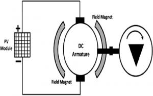
As the current-carrying conductors are placed under the magnetic field they experience a force according to Lorentz force. Here, The force direction can be found by the rule of Fleming’s right-hand. The direction of force enables the coils to develop a Uni-directional torque that enables the rotor to rotate. The DC motor working is shown in the following figure.
working of DC motor
Types of DC Motors
There are different types of DC motors available. They are
- PMDC type
- Separately excited
- Self-excited
The classification of self-excited can be done like the following.
- Shunt-wound
- Series wound, and
- Compound wound type.
Again, the compound type can be classified into two types namely long shunt as well as the short shunt. The long shunt is further classified as cumulative and differential types. Similarly, the short shunt types are further classified as cumulative and differential types.
The separately excited and series types are commonly preferred for industrial purposes. The DC motors classification figure is shown below.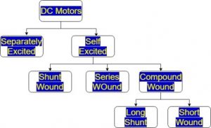
PMDC Type
PMDC stands for permanent magnet DC motor. It works on the same principle as that of a normal type. The difference between the normal type and PMDC is the usage of permanent magnets for the production of the magnetic field instead of using a field coil in series with the armature winding. The permanent magnet produces the field flux and the flux produced by the armature interacts with each other to produce a resultant magnetic flux. This resultant flux is considered to be as the armature reaction. This enables the coils to produce a Uni-directional torque. The PMDC type motor working is shown in the below image.
pmdc Motor Working
Separately excited
The field winding of the machine requires a separate source to supply. It also requires a supply for the armature. Hence, two DC supplies are required for its operation. This type is also called a servo type motor.
The separately excited type motor equivalent circuit diagram is illustrated below.
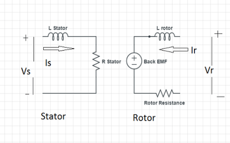
The equivalent of Separately Excited DC Motor
The voltage equation of separately excited type machine is given as
V = Eb + Ia Ra + Vbrush
We can neglect brush loss, then we get
V = Eb + Ia Ra
Self-excited
The field winding of the machine does not require any separate source. It feeds the supply on its own by the use of armature. The supply to the field winding is received from the armature voltage. The self exited type diagrams of shunt-wound type, series type, and compound type are shown below.
Please refer to this link to know more about DC Motor MCQs
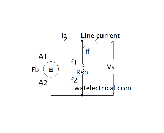
Shunt Wound Type
It is considered as shunt type because the field winding is connected in parallel with the armature winding.
V = Eb + Ia Ra + Vbrush
Il = Ia + If
If = Vs / Rsh
The flux in this type is directly proportional to the field current If a relationship is expressed as
Φ α If
If is constant because the Vs is kept constant,
The circuit of the shunt-wound type motor is shown in the figure below.
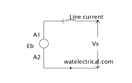
Series Wound
It is considered as a series type because the field winding is in series with the armature winding. The series-wound type diagram is illustrated below.
The voltage and current equation association is given as
V = Eb + Ia Ra + Ia Rse + Vbrush
V = Eb + Ia +(Ra + Rse) + Vbrush
The brush losses can be neglected then the equation obtained is as follows
V = Eb + Ia +(Ra + Rse)
The current in the series type connection is as follows
Ia = Il = Ise
The relationship between the flux and the field current is given as
Φ α Ise
The flux is directly proportional to the series field winding.
Whenever load increases, the flux leftovers constant subsequent to saturation. The series-wound type of motor image is displayed below .
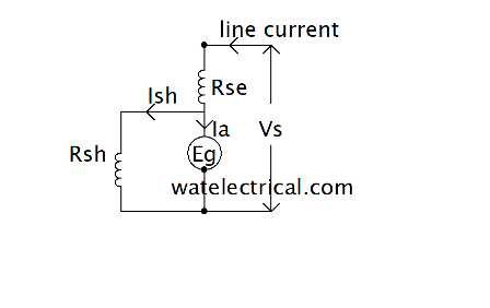
Long Shunt Wound
The diagram of the long shunt-wound is shown in the below.
The association between and current and voltage is expressed as
V = Eb + Ia Ra + Ia Rse + Vbrush
The brush drops can be neglected, then we get
V = Eb + Ia +(Ra + Rse)
Ia = Il – Ish
Ish = V / Rsh
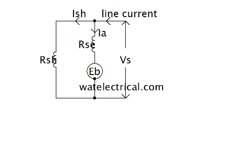
Short Shunt Wound
The diagram of short shunt type motor is illustrated below.
The relationship between and current and voltage is expressed as
V = Eb + Ia Ra + Il Rse + Vbrush
The brush drops can be neglected, then we get
V = Eb + Ia Ra + Il Rse
Ia = Il – Ish
Ish = V – Il Rse / Rsh
The circuit of shunt-shunt wound type is given below.
Therefore, this article includes the classification of DC motors. This classification is based on the different types of placement of the winding and accordingly, the motors are categorized. And also discussed the basics of DC motors, PMDC motors, separately and self-excited motors. Here is a question for you, what are the applications of a cumulative compound DC motor?
Picture Credit : ResearchGate