The operational amplifier or op-amp is a versatile & very efficient device. The op-amp is used to amplify the weak signal and it can be made simply into various forms based on the requirements of the circuit. One of the forms is the voltage follower. Here voltage follower is mainly used for isolating the signal as well as improving load capacity and this is also known as a unity-gain amplifier, isolation amplifier, or buffer amplifier. In a voltage follower op-amp circuit, the output voltage is equivalent to the input voltage; so, it has unity gain & does not strengthen the incoming signal. This article discusses an overview of a voltage follower – circuit & its working.
What is a Voltage Follower?
A voltage follower is an op-amp circuit where the output voltage of this circuit is equivalent to the input voltage which means the output voltage follows the input voltage. Thus this op-amp does not strengthen the input signal, so the voltage gain of this is ‘1’. The main characteristic of this circuit is very high input impedance so it can be used in different kinds of circuits that need isolation between the input & output signal.
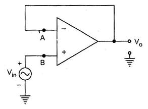
The basic voltage follower op-amp circuit is shown below. Node ‘B’ is there at potential ‘Vin’ and node ‘A’ is also at a similar potential as ‘B’ that is Vin.

Voltage Follower Circuit
VA = VB = Vin ……(1)
The node ‘A’ is connected directly to the output. Thus we can write it as
V0 = VA …..(2)
By equating both the above equations like 1 & 2 then;
V0 = Vin ….(3)
So, the voltage gain for the above circuit is unity.
Therefore, the o/p voltage like ‘Vo’ is equivalent to the i/p voltage like Vin. When Vin increases, then Vo also increases. Similarly, if ‘Vin’ reduces, then ‘Vo’ also reduces. So the output simply follows the input so the circuit is known as a voltage follower circuit. This circuit is also called a unity gain amplifier, source follower, isolation amplifier, or buffer amplifier. The input & output waveforms are given below.
What is the Purpose of a Voltage Follower?
A voltage buffer amplifier is used to transfer a voltage from a first circuit, having a high output impedance level, to a second circuit with a low input impedance level. This is used as a buffer to draw extremely less current because of the amplifier’s high input impedance so, it eliminates the loading effect while still maintaining a similar voltage at the output. The voltage follower has no voltage gain.
Voltage Follower in Voltage Divider Circuits
The voltage in any electronic circuit is shared with the resistance or impedance of the connected components. Once an op-amp (operational amplifier) is connected within a circuit, then a large voltage drop will occur across it because of its high impedance.
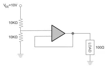
Thus, if we utilize voltage follower within voltage divider circuits, it will allow sufficient voltage to supply across the load. So let us discuss a voltage follower in the voltage divider circuit as shown below.

Voltage Divider Circuit
In the above circuit, the voltage divider is in the center of two resistors as well as the operational amplifier. This amplifier provides some hundreds of megaohm input resistance so we can assume it is 100 MΩ. Thus the equivalent parallel resistance is 10 KΩ || 100 KΩ.
The equivalent parallel resistance = 10-kilo ohm X 100 mega ohm/10-kilo ohm + 100 mega ohm
= 9999 ohms or 10-kilo ohms.
We know that the voltage divider circuit includes two similar resistances and provides accurately half of the voltage. By using the voltage divider formula, we can prove it as follows.
V output = V input X R2/ R1 + R2
= 10V x 10 kilo ohm/10 kilo ohm + 10 kilo ohm = 5V.
Therefore, this 5Volts voltage drop will be across the top, and bottom of 10KΩ resistance & the 100Ω load resistance. We have observed how the operational amplifier functions as a buffer to get the preferred voltage to the load connected.
If the voltage follower is not there within the voltage divider circuit, then it will not work because of the lack of enough voltage across the connected load.
The main reason to implement the voltage follower in the voltage divider circuit is mainly for two purposes. One is for isolating purposes & another purpose is for buffering the o/p voltage from an electronic or electrical circuit to obtain the preferred voltage to the load connected.
Voltage Follower Circuit with 741 IC
The voltage follower circuit using 741 IC is mainly designed to provide unit gain output. We know that the voltage follower op-amp circuit gives an output similar to the input signal. In this circuit, the 741 IC is used as an op-amp. This 741 IC is a dual inline packed (DIP) 8-Pin based IC which provides high gain output. This IC includes two input terminals Inverting like Pin 2 & Non-Inverting like Pin 3 & one output terminal like Pin 6.
This 741 IC operates by using a battery power supply or dual power supply. This IC can work as a comparator, integrator, multivibrator, differentiator, active filter, etc.

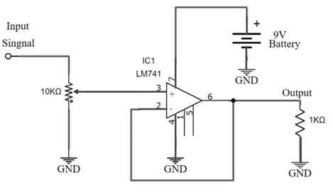
Voltage Divider Circuit with 741 IC
The required components to design this circuit are LM741 IC, 10KΩ variable resistor, 1KΩ resistor 1KΩ, 9V battery, and the source of the input signal from a function generator.
Circuit Working
Connect the circuit as per the circuit shown above. The working of this circuit is, whenever the Input signal is applied to pin3 & Pin2 is connected with Pin 6 (output) to make negative feedback. The bias pins are simply connected to a battery whereas the output is simply connected to the load resistor.
The op-amp’s input impedance will be extremely high up to 1MΩ once we implement it within the circuit. Because of the high input impedance, an extremely low current supply will be drawn from the source of input and provides high output current to the load. So here, the output impedance will be extremely low. The voltage, current & resistance can be calculated with the help of ohms law (I = V/R).
Here the voltage follower circuit provides equal output voltage like input voltage however it draws low input current from the source of input because of high input impedance & provides high output gain because of the low output impedance. So due to the same level of input & output, it is simply known as a unity gain amplifier.
Voltage Follower Stability
Generally, a voltage follower circuit is used to produce an output signal which follows the input signal. However, the main problem here needs to consider the stability of the circuit as the device is vulnerable easily to oscillations. So this shows an effect on the stability of the voltage follower.
Oscillations within the negative feedback-based amplifiers are related to the phase shift wherever this activates negative feedback to turn it into positive feedback. A voltage follower op amp circuit responds easily to oscillations as compared to any other circuits which have high gain values.
In many of the situations, it is desirable to remove oscillation within the circuits & the op-amp is chosen which has unit gain stability. So these op-amps are compensated internally by producing a frequency response, which allows for good stability even once the machine is used in any of the devices with voltage-follower configuration.
Advantages of Voltage Follower
The advantages of voltage follower include the following.
- The voltage follower simply removes the loading impact.
- They have high i/p impedance & low o/p impedance.
- The transmission gain of this voltage follower is unity.
- The input signal’s amplitude does not increase or decrease by the voltage follower circuit.
- It provides current gain & power gain.
- Loading effects will be avoided.
Applications
The applications of voltage follower include the following.
- For logic circuits, voltage followers are used as buffers.
- These are used in sample & hold circuits.
- These are used in active filters.
- These are used in bridge circuits through a transducer.
- A voltage follower circuit is mainly used for creating isolation between two different types of circuits.
- Voltage followers are mainly used between two networks for decreasing the loading on the primary network.
Thus, this is all about an overview of voltage follower operational amplifier–circuit, working with applications. Here is a question for you, what is an operational amplifier?