Resistor, the most and crucial electronic component which is used in almost every electronic device. Even though our today’s discussion is on pull-up and pull-down resistors, the first and fundamental concept that we need to know is what is a resistor. So, a resistor is the two-terminal device which are used for the measurement of resistance. In the circuits, these resistors are used for the purpose of controlling current levels, voltage distribution, signal leveling, and many others. These components can also be implemented as a part of integrated circuits. So, knowing the operation of a resistor, let us continue to know about pull-up and pull-down resistor, their circuits, and applications.
What are Pull Up Resistors?
Pull-up resistors are defined as resistors that make sure to drag the wire to higher logical levels even any input signal is not present. These resistors are employed in the logical circuits to make sure of well-specified logical values for a specific pin at any condition. We know that a digital circuit operates in three states and those are floating, high and low. The floating state takes place when the pin is not either at HIGH or LOW but at other values. So, in this condition, pull-up resistors are implemented to resolve the problem by dragging the pin either to digital HIGH or digital LOW logic levels.
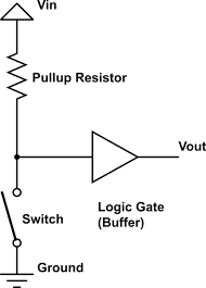
If in the case when pull-up resistors are not there, then the pin would be in the floating state when the switch is opened and only moves to a lower state when the switch is closed. These pull-up resistors are considered as the resistors having a constant value that is used as a connection between the corresponding pin and digital HIGH logic level. This helps in specifying either input or output values even any driving signal is not there. In general, a pull-up resistor has a value of 4.7kΩ and it gets varied based on the specific application. The basic pull-up resistor is shown below:

Basic Pull Up Resistor
The exact value of the pull-up resistor is constrained mainly by two factors. One is power dissipation which means that when there is minimal resistance, current flow increases across the pull-up resistor which heats the device and uses additional power in the closed state of the switch. This scenario is termed as a string pull-up. While the second factor is the pin voltage which is the condition in the OPEN state of the switch. When there is an increased pull-up resistance value along with the high leakage current in the input pin, then the input voltage level is deficient in the OPEN condition of the switch. This scenario is called a weak pull-up.
NAND Gate Circuit Using Pull-Up Resistor
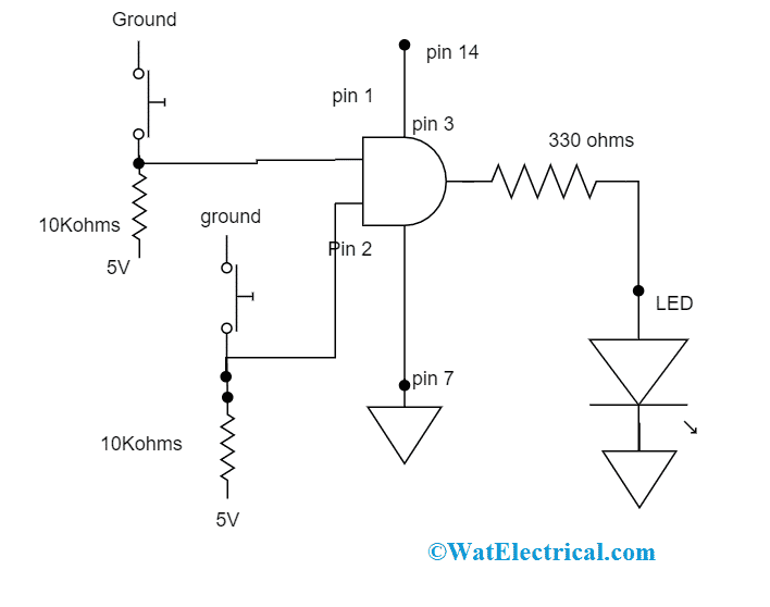
NAND circuit can be implemented with two pull-up resistors and these are at the input side. Here, the circuit connection is done in the way that the power supply is given to the 14th pin and the 7th pin is connected to the ground. This supplies power to the IC.

NAND Gate Circuit
Then, both the pull-up resistors are connected to both the inputs of the NAND gate. In this pull-up resistor, a resistor will have a connection with a positive voltage level, and a push-button is connected to the ground. NAND gate pins will be at logic HIGH when the push button is pressed. Whereas when it is pushed down, the pin will go in direct contact with that of ground and moves to digital logic LOW. As per the operation of the NAND gate, when either of the inputs is LOW, the output state will be HIGH. So, only when both the pushbuttons in the circuit are not pressed, then the output is LOW and the LED gets OFF. In the same way when both the pushbuttons in the circuit are pressed, then the output is HIGH and the LED gets ON.
What are Pull-Down Resistors?
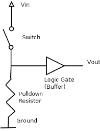
The operation of pull-down resistors is almost similar to pull-up resistors. Pull-down resistors are defined as the resistors that make sure to drag the wire to lower logical levels. They have a connection between a specific pin and the ground. The operation can be explained in the way that the push button has a connection to the corresponding pin and the power supply.

Basic Pull Down Resistor
Here, the pin goes to the logic HIGH state, when the switch is in a closed condition, and in the open condition of the switch, the input voltage of the pull-down resistor moves to the logic LOW state. Here, the resistor should have maximum resistance than that of the circuit impedance, if not the input voltage at the pin will be a constant (logic LOW) irrespective of the switch position.
Please refer to this link to know more Resistors MCQs
AND Gate Circuit Using Pull-Down Resistor
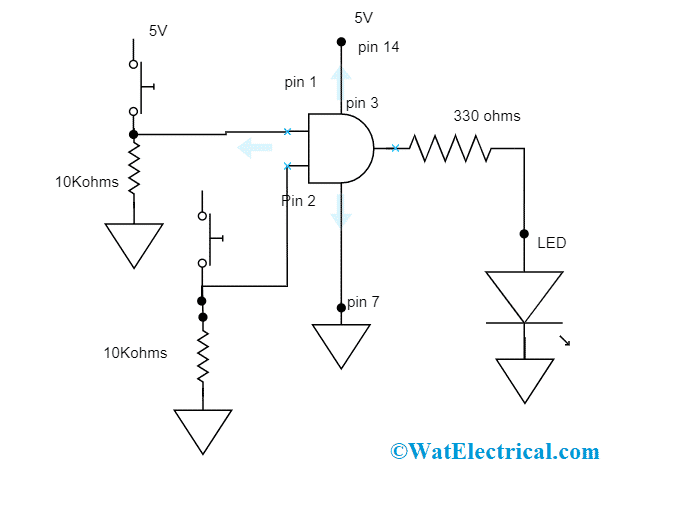
AND circuit can be implemented with two pull-down resistors and these are at the input side. Here, the circuit connection is done in the way that the power supply is given to the 14th pin and the 7th pin is connected to the ground. This supplies power to the IC.
Then, both the pull-down resistors are connected to both the inputs of the AND gate. In this pull-down resistor, the push-button has a connection to the positive voltage level and the 10KΩ resistor is connected to the ground. AND gate pins will be at logic LOW when the push button is not pressed. Whereas when it is pushed down, the voltage drop across the resistor happens and the digital logic HIGH is the output. As per the operation of the AND gate, when both the inputs are HIGH, the output state will be HIGH. So, for the circuit operation, both the pushbuttons have to be pressed down.
Calculation of Resistor Values
So, we are clear about the operation of both the resistors. Now, we will move to know the value of both these resistors. Even though in most of the digital circuits, these resistors operate in the range of 2 – 4.7k, the exact value is not known. So, with the below procedure the exact value of the resistors can be known. For this, what value of voltage is considered as LOW and what is considered as logic HIGH. Each kind of microcontroller works on various logic levels.

AND Gate Circuit
When a TTL logic is used, the below are the voltage levels.
So, 0.8V is considered as the logic HIGH and below this value, it is considered as logic LOW. In addition, when the supply voltage is in the range of 2 – 5.25V, it is treated as HIGH. In between 0.8 – 2V, the region is NULL, and neither HIGH nor LOW is not considered.
As per ohm’s law, the pull-up resistor value is as below:
Rpull-up = [Vsupply – VH(min)]/ Isink
And for pull-down resistor, the value is
Rpull-down = [VL(max) – 0]/ Isource
Here,
‘Vsupply’ is the supply voltage
‘VH(min)’ is the accepted voltage level
Isink and Isource are the maximum sinked and sourced by the pin
Applications
The applications of pull up and pull down resistors are discussed below.
These resistors are used at the time of switch interfacing or in any digital gates. Many of the MCU’s have already assembled with pull-up and pull-down resistors so only minimal devices are required. When compared with pull-down, pull-up resistors have extensive applications. These are implemented in ADC’s to offer a regulated current flow into the resistive sensor devices.
The next application of these resistors is on the I2C protocol bus. Here, to enable a pin to operate either as input/output, pull-up resistors are used. If not connected, the pin moves into the maximum impedance condition. Whereas, to offer output impedance, pull-down resistors are even employed on outputs.
So, this is all about the concept of pull-up and pull-down resistors. Know further on what are the open-collector outputs in pull-up/pull-down resistors?