When a number of capacitors are connected together it forms a capacitor bank. They can be connected in series or parallel. A capacitor bank has numerous advantages and applications. Most of the time, these are used for reactive power compensation and power factor improvement. The arrangement of these can be done at substation or power plants. The unit for capacitance in Farads. A capacitor bank of lower scale is frequently used in industrial buildings, college campus, large residential communities to improve power factor. The necessity of improving the power factor is very critical, as a low power factor at one point would disturb the power balance among the vicinity and would also attract penalties from local electrical distribution companies.
Capacitor Bank Definition
When a number of capacitors are connected together in series or parallel, forms a capacitor bank. These are used for reactive power compensation. Connecting the capacitor bank to the grid improves reactive power and hence the power factor.
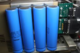
Capacitor Bank
As shown in the figure, capacitors are connected in series to improve the power factor rating. Different materials like paper, mica, etc. are used for the manufacturing of the capacitors as insulating materials.
Capacitor Bank Symbol
This symbol is often used in a single line diagram of the substation. The symbol is shown in the following figure.
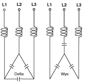
Capacitor Bank Symbol
As shown in the figure, a capacitor bank is represented either in star or delta connection.
Capacitor Bank Types
The capacitor bank is classified as:
- Externally Fused – For this type of connection, each fuse unit is connected externally to the capacitor bank. This helps to save the capacitor bank from faults like surge voltage, temperature, etc. without any interruption in the operation.
- Internally Fused – In this type, the fuse is kept inside the casing of the capacitor bank. Since the protection cannot be provided without any interruption, such banks are used for low rating capacitor banks. The disadvantage of such an arrangement is, under any fault case, the whole unit has to be replaced.
- Fuse Less – This unit has no fuse placed along with the bank. These units are used for low ratings and specifications where the unit can be easily replaced.
Capacitor Bank Calculation
The calculation is an important feature that needs to be considered while designing a substation or residential community. The steps involved in the calculation are as follows.
To calculate the rating of the bank, we must have the following data available directly on indirectly. First is the power factor. The present power factor must be calculated to know the desired power factor. This can be done by using a power factor meter. The power factor meter is an instrument that measures power factor cos ø based on load and active power consumption.
Based on the active and reactive power consumptions, the power factor can be calculated as
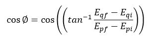
Epi and Eqi are the values of active and reactive power respectively. These values are measured initially or at the beginning of one cycle. The cycle refers to a period, it may be a day or a few hours. Similarly, Epf and Eqf are the values of active and reactive power at the end of the cycle. Once we get these four values, we can calculate the initial value of the power factor.
Once the present value of the power factor is known, next is to know the desired power factor. That is the power factor that we want to obtain. Let the initial value be cos φ1 and the desired value is cos φ2. From the initial and final values of power factor, active power P can be evaluated as shown in the below figure
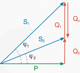
Power Diagram
As shown in the figure, φ1 is the initial power factor angle and φ2 is the final power factor angle. From these two, active power P can be evaluated. After evaluating P, the required reactive power rating of this can be calculated as
Qc=KP
Where ‘Qc’ is the required rating of the bank, P is the active power rating of the load, and K is constant. To evaluate the constant a power factor table is followed.
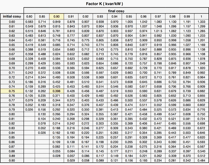
Power Factor Correction Table
From the above table, from the initial and final values of the power factor, constant K is evaluated and the required rating is calculated.
Example
Find the rating of required capacitor bank for a plant with rating 300 W, 400 V. Initial power factor angle is Cos φ1 = 0.75 and desired is Cos φ2 = 0.9.
From the table, it can be seen that with the initial power factor 0.75 and desired power factor 0.9, constant K is 0.398. Hence the required reactive power rating of the bank to improve the power factor from 0.75 to 0.9 is 0.398*300= 119.4 KVar.
Capacitor Bank in a Substation
As we have seen that one major role of this is to improve the power factor. For this application, these banks are installed in substations. A number of capacitors are connected in series to improve the voltage profile also. As can be seen in the power factor angle above, on installing this bank, the capacitor current which is also known as charging current, is always leading with the voltage.
On the addition of the capacitor bank, the current leads the voltage, hence the power factor angle is reduced. Reduction in power factor angle implies, improvement of power factor. This becomes very important, as it also provides reactive power compensation. Reactive power compensation is the other outcome of improvement in the power factor.
Installing inductive loads on the load side demands more reactive power. Since inductive loads consume reactive power for creating the required magnetic flux. More the inductive nature of the load more is the requirement of reactive power. In other words, inductive loads, consume reactive power. As the reactive power is consumed, the load becomes more lagging, and hence power factor drops. Consumption of reactive power causes an imbalance in power consumption and hence causes more losses. This would increase the burden on the plant.
Installing this will helps to inject reactive power into the system. As reactive power is injected, it improves the power balance and hence reduces the losses. It also helps to improve the efficiency of the plant.
Capacitor Bank Specification
We have seen that a capacitor bank is used for the improvement of power factor and reactive power compensation in a substation. As the role of this bank is very important, it becomes critical to see that the bank is maintained well. Also, it has to be seen which parameters of this bank should be specified for installing it into the substation.
Important Specifications are
- Voltage Rating – The voltage rating of this is designed up to 110% of normal system peak voltage and 120 % of normal system RMS voltage. This rating helps the bank to sustain voltage peaks and surge voltages.
- KVaR Rating of Capacitor Unit – Based on the initial power factor and desired power factor, the reactive power rating of this is calculated. It is ensured that with this rating sufficient reactive power is injected into the system.
- Temperature Rating – In order to sustain room temperature, and an increase in temperature due sunlight the temperature rating of this bank is calculated. While considering the temperature rating all these factors must be considered. One more important factor is the increase in temperature due to losses.
- Basic Insulation Level – Like any insulating medium, the insulating medium of these banks is also considered. The insulation level is an important factor. Other devices where this parameter is also considered are overhead insulators, transformer oils, etc.
- Rated Current Levels.
- Discharge time/voltage in second/voltage
- Single-phase and three-phase
3 phase Capacitor Bank Wiring Diagram
The wiring diagram of the three-phase capacitor bank is shown below.
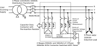
Three Phase Capacitor Bank Wiring Diagram
As shown in the above figure, 2 capacitor banks have been connected to the grid. All these are connected in delta. In the delta, the line voltage is equal to the phase voltage. This helps in improving the power factor.
Applications
Some of the important applications of capacitor bank have been listed below
- Reactive Power Compensation
- Power Factor Improvement
- Bypassing of noise
- Improvement of voltage profile
- Storage of Energy
- Improving power quality
FAQs
1). Why do we use a capacitor bank in substation?
These are used for reactive power compensation and power factor correction.
2). Will a capacitor bank save on electricity?
Yes, installing a capacitor bank improves the power factor. Less power factor causes more losses and attracts fine from the local electricity board. So by installing this we can save electricity.
3). What is the purpose of the capacitor bank?
It is used for power factor correction and reactive power compensation.
4). What happens if I connect a capacitor to the generator load?
Both capacitors and generators inject reactive power into the system. So connecting a capacitor to the generator load increase the reactive power level. This may also cause instability. For this purpose, shunt reactors are used which consume excess reactive power.
5). How do I test a capacitor with a multimeter?
The capacitance of a capacitor can be measured using a multimeter. For this, we need to put the range of the meter in high ohm value such that, it can measure capacitance in farads.
Hence we have seen the capacitor bank purpose, operation, connections, and applications. The capacitor banks are one of the handiest devices required in not only in substations but also in residential establishments and industries. Two interesting aspects with respect to this are left to the reader to think about. One is what is the ideal placement of capacitor bank? It means that where should the bank be placed, at the beginning of the plant, or midway or endpoint. The other aspect is can we control the capacitance of the capacitor bank? If yes then which auxiliary devices we should use for it.