These days, the scope of the entire technology revolves around electric devices, machines, and circuits. For all these, electricity stands as a fundamental component. The enhancement and the progression of multiple phases in electricity increased the development of many electric devices. Of many devices, the one which grabs the attention of many customers to implement in their industries is “Rheostat”. Being in optimization with the recent trends and technologies, this device suits well for many requirements and desires. So, this article gives a clear idea regarding the concept of the rheostat, its working and other related.
What is a Rheostat?
Rheostat Definition: It is a type of varying resistance device which is employed to regulate current flow. When there happens a situation to modify the resistance values in a circuit, this variable resistor holds the ability to handle delivering no flaws and issues. Either to increase or decrease the resistance levels, how it functions well and shows accurate results. As we know that the flow of current is decided through the applied voltage and resistance, it is more crucial to know how this rheostat function and controls.
When the device is placed in the circuit, one can easily manage the levels of current flow. This device can regulate current flow to some extent, but it does not hold the complete ability to obstruct the flow of current. In practical applications, there exists no possibility to obstruct the complete flow of current.
Rheostat Construction
In similar to the construction of potentiometer, a rheostat is also constructed. This device is constructed with three terminals named A, B and C. The operation is done only with two terminals either (A & B or B & C). The track is the connection where the terminal A and C are connected, and these are the fixed terminals whereas terminal B is the changeable terminal, and this has a connection to the slider or else sliding wiper. The movement of the wiper in the circuit decides the resistance value across the rheostat. This resistive component is constructed either with a slender carbon film or with a wire coil. For the purpose of winding, either ceramic core or nichrome wires are used. As these materials are the heat insulators, they are non-conductors of heat. The diagram is shown as below:
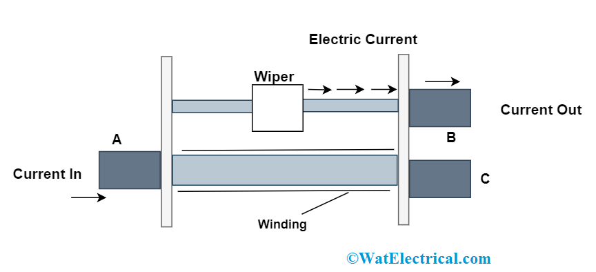
rheostat-diagram
Rheostat Working
A per the rheostat connection, the working principle of this device can be explained as below:
Scenario 1
The resistance values in the device are known by the resistive track length where there is the flow of current. When A & B terminals are used for operation in the device, the output will be less when the wiper is moved towards A terminal where because the resistive path length reduces. Due to this, there will be only a minimal amount of current blockage and more amount of current passage through the device.
In the same way, when the wiper is moved towards the C terminal, the output will be maximum where because the resistive path length is more. Due to this, there will be only a minimal amount of current passage and more amount of current blockage through the device.
Scenario 2
When B & C terminals are used for operation in the device, the output will be less when the wiper is moved towards the C terminal where because the resistive path length reduces. Due to this, there will be only a minimal amount of current blockage and more amount of current passage through the device.
In the same way, when the wiper is moved towards A terminal, the output will be maximum where because the resistive path length is more. Due to this, there will be only a minimal amount of current passage and more amount of current blockage through the device.
So, it has to be noted that there is no utilization of either a resistive route or wire, only based on the resistive path, there is a change in the output resistance values.
Symbol
The rheostat symbol can be depicted as follows:
As per the American standard, the device symbol is shown as zigzag lines along with the representation of three terminals and it is like
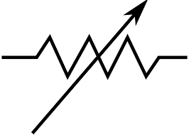
American-standard-of-rheostat
Whereas as per the International standard, the device symbol is shown as a rectangle-shaped box along with the representation of three terminals and it is like
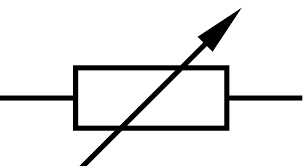
international-symbol-of-rheostat
Rheostat Applications
The rheostat is mostly employed in the situations of maximum current and voltage necessities.
- The fundamental application of these devices is to change light brightness levels. It operates in the scenario that when the resistance is amplified, current flow in the light gets reduced and so intensity decreases. In the same way, when the resistance is decreased, current flow in the light will be increased and so intensity increases.
- They are probably employed for power regulated devices like to regulate the speed of motors, ovens, geysers, and heaters.
- As this device has minimal efficiency, most of the applications that need power adjustment will not use these but used to some extent.
- Implemented in the circuits that require tuning because of irregular resistance along with the calibration. The devices are altered in these cases when the circuit is not tuned at the time of the manufacturing process.
Difference between Rheostat and Potentiometer
The basic difference that has to be noted is that potentiometer is employed to determine the unknown emf values thus regulates the electronic circuit voltage, whereas rheostat is employed to regulate the current flow.
Rheostat | Potentiometer |
| In this, current flow can be regulated by altering the resistance values | By comparing with the unknown voltage levels, unknown emf value can be determined |
| It comes under the classification of a variable resistor | It comes under the classification of a sensor device |
| A rheostat is either a 2 o3 3 terminal device where the connection is with one terminal and the other with slider. Rheostat regulates the flow of current | The potentiometer has 3 terminals where the ends are connected along with the wiper and the circuit. Potentiometer regulate the flow of voltage |
| A rheostat is used for applications that use high power.
| A potentiometer is mostly employed for the applications that use low power |
| The rheostat is constructed with metallic ribbon or carbon disks.
| A potentiometer is made up of graphite material |
| Rheostat in series connection with the circuit.
| A potentiometer is connected parallelly with the circuit |
On the whole, both the devices have just slight variations and each one holds their own advantages and applications. Based on the requirement and implementation, the device is selected.
FAQs
1). What is a rheostat made of?
In general, rheostats are constructed thin carbon sheets or winded with nichrome wire throughout the insulating ceramic material.
2). What is the difference between rheostat and potentiometer?
The basic difference that has to be noted is that potentiometer is employed to determine the unknown emf values thus regulates the electronic circuit voltage, whereas rheostat is employed to regulate the current flow.
3). Does rheostat change voltage?
When a rheostat is placed close to the voltage source, there will be current variation and the voltage is constant.
4). Which wire is used in rheostat?
Mostly, Nichrome wire is used in the construction of a rheostat
5). Why rheostat is used in Ohm’s law?
As per the principle of Ohm’s law, the voltage and current relationships in a rheostat can be known through this.
So, this is all about the theory behind rheostat. This article has provided a detailed scenario on the concepts of how rheostat operates, what is its working principle, its connection, circuit and all. As because of its uses and benefits, it is widely employed in many domains.