We all know that amplifiers hold great prominence in the scope of the electrical and electronics industries. Moving in this scenario, today our discussion will be on an integrated circuit which is LM386. It is the IC including a low voltage audio power amplifier. This IC was initially invented by Ernie Leroy Long in the year 1969 and the first application of this device was as a fuel injection system in the Ford car. There exist various models of LM386 that have somewhat different specifications. Let us move ahead and know clearly on the LM386 audio amplifier, pin diagram, features, specifications, and applications.
What is an LM386 Audio Amplifier?
It is the low voltage power amplifier designed exclusively to implement in the minimal voltage required consumer applications. It is a mini 8-pin DIP package with having body size of 9.60mm×6.35mm. Initially, the gain of the device is maintained at 20, but adding external components such as a capacitor and resistor in between 1 and 8 pins will enhance the gain values from 20 to 200.
The output is automatically biased to half of the provided voltage whereas the inputs are ground connected. To construct an LM386 based audio amplifier, just a few components of resistors and capacitors are enough. The chip can also be converted into an oscillator which holds the ability to deliver either square or sine waves. Mainly there are three types of LM386 chips which have different power ratings and those are:
- LM386N-1 delivers 0.325 watts of power
- LM386N-3 delivers 0.700 watts of power
- LM386N-4 delivers 1.00 watts of power
Electrical Characteristics and Features
The features of LM386 are
- Operated with batteries
- Requires few components for the construction of the device
- Extensive range of power supply (4-12V or 5-18V)
- It has a minimal quiescent current drain of 4mA
- Voltage gain varies in the rage of 20 to 200
- It has input as ground-referenced
- Minimal distortion levels of only 0.2%
- It is also available in 8-pin MSOP package along with DIP package
As per the LM386 datasheet, the electrical characteristics of LM386 are
| Parameter | Representation | Min | Max | Measured Units |
| Functional voltage levels | Vs | 4 and 5 | 12 and 18 | V- Volts |
| Output power | Pout | 250, 500 and 700 | – | mW – milliWatts |
| Bandwidth | BW | 300 | – | kHz – KiloHertz |
| Voltage Gain | Av | 26 and 46 | – | dB |
| Total Harmonic Distortion | THD | 0.2% | – | – |
| Input Resistance | Rin | 50 | – | kΩ – kiloOhms |
| Input Bias Current | IBIAS | 250 | nA |
Pin Configuration
As LM386 has an 8-pin DIP package, the pin configuration of this IC can be explained as follows. Here, we shall have a detailed discussion of all pins and their functionality.
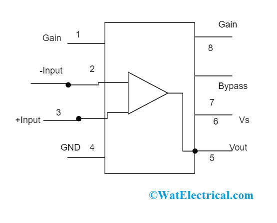
LM386 Pin Diagram
Pin 1 and Pin 8 – These are the gain regulation pins where the chip gain is internally set to 20 but adding of external components such as capacitor and resistor in between these pins will enhance the gain values from 20 to 200. To achieve maximum gain, a capacitor of 10µF is used.
Pin 2 and Pin 3 – These are considered as input pins for audio signals. Here, pin 3 is the positive terminal where the required signal that has to be amplified is fed to it, and pin 2 is the negative terminal and is ground connected. The input signal is fed to the +ve terminal through 100k potentiometer and this connection operates as volume regulating knob. Also, a capacitor of value 0.1µF is added to eliminate any kind of DC factor from the input signal.
Pin 4 and Pin 6 – These pins supply power to LM386 IC, one is connected to +Vcc and the other to the ground. The power supply range for this IC lies between 5 to 12v.
Pin 5 – The output is received through pin 5 and it is the amplified audio signal. As the output signal consists of both DC and AC components, we need to eliminate the DC factor and it can be done by inserting a capacitor of 220µF.
In addition to this, a circuit of the resistor of 10k and a capacitor of 0.05µF is used as a filter to eliminate any kind of noise or oscillations. And this circuit is termed as Zobel network.
Pin 7 – This is called the bypass terminal. It can be either grounded through the capacitor or kept as left open.
| Pin number | Name | Type | Description |
| 1 | Gain | Gain set up | |
| 2 | -ve input | I/P | Inverting |
| 3 | +ve input | I/P | Non-inverting |
| 4 | Ground | P | Ground connected |
| 5 | Output voltage pin | O/P | Output |
| 6 | Source voltage pin | P | Power supply |
| 7 | Bypass | O/P | Bypass terminal |
| 8 | Gain | – | Gain set up |
The detailed LM386 pin configuration is
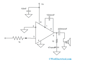
LM386 Audio Amplifier Circuit Diagram and Working
In the circuit diagram of LM386, when the gain setting pins are open, then the gain will be 20 and it is set up by 1.35kW internal resistances, Or else in between the gain setting pins when a capacitor is placed, this bypasses the internal resistances and the gain reaches to 200. To achieve the desired amount of gain, below are connection types using resistors or capacitors.
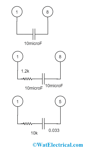
Circuit Diagram
With the first circuit that is mentioned below, a gain of 200 can be achieved and with the middle circuit, the gain of 50 can be achieved. While selecting the last circuit a gain of approximately 5dB can result. To achieve 5dB gain, the resistor and capacitor have to be connected between pin 1 and pin 5. As we have already discussed that gain can be adjustable in the range of 20 to 200 by inserting a potentiometer of 4K7 in series connection with the capacitor.
Additional offset factors can also be eliminated by including an idle input to the resistor from the ground. Also, the entire offset factor is eliminated when the input is connected by using a capacitor. When the circuit’s gain is set to 200, it is important to make pin 7 as bypass terminal through a 0.1µF capacitor and this achieves stability by reducing noise and oscillations. As stated above, when the gain is 5dB, it is termed as a bass boost network. The delivered output will be across 550MW when a speaker of 16Ω impedance is connected.
LM386 is the audio power amplifier that also functions as an operational amplifier. It means in the way that it is configured like a power oscillator in the alarm and also when switches are added it delivers multi-tone.
So, this is an LM386 based audio amplifier: circuit and working.
Please refer to this link to know more about operational amplifier MCQs
Gain Control
Making this IC So exclusive, the pins 1 and 8 are there where those pins regulate gain. when the gain setting pins are open, then the gain will be 20 and it is set up by 1.35kW internal resistances, Or else in between the gain setting pins when a capacitor is placed, this bypasses the internal resistances and the gain reaches to 200.
The gain regulation can also be achieved by capacitive coupling or creating an FET circuit in-between ground and pin 1. To make this LM386 amplifier function for required applications, other components can also be included in parallel connection to that of feedback resistors to achieve the required frequency response and gain values. This is the gain control of LM386.
Gain Control Of LM386
For instance, by frequency shaping the feedback loop, poor signals in the speaker can be amplified. This is achieved by having a series connection between pins 1 and 5.
Input Biasing of LM386
From the above circuit diagram, we can observe that the inputs of the device are ground biased using a 50kW resistor. As the base current at the transistors at the input side is 250nA, these have 12.5mV when they are in an open condition.
When the DC source resistance that drives the IC is >250kW, then it results in minimal additional offset (which is almost 2.5mv and 50mV at input and output). Or else when the DC source resistance that drives the IC is <10kW, then the idle input will maintain the offset as minimal.
Applications of LM386
In consideration of this IC, the applications of this device are:
- Employed in line and ultrasonic drivers
- Intercommunication systems
- Implemented in audio and radio amplifiers
- TV sound circuits
- Used for power conversion systems
- Small tape-recording amplifiers
List of Sample Projects
With this IC many LM386 projects can be constructed and few of those to be listed are
- PC-FM radio circuit
- Intercommunication circuit
- Electric siren having multi-tone
- IR detector system
On the whole, this is comprehensive information about the LM386 amplifier. The many other topics to be known are what is LM386 calculator, LM386 comparator, Lm386 alternative, and LM386 vs LM?