An electrical generator is one kind of electrical machine, used to convert input mechanical form energy to electrical energy either AC (or) DC. Depending upon the output it is classified as an AC generator or a DC generator. The DC generator consists of a Yoke, armature core, pole core, bearings, brushes, and a commutator. Each component of the DC generator has its individual role to play in the operation. Among them, the working of a commutator is very important. As any machine delivers its output as an alternating power. Here, the commutator converts this alternating power to the required DC power in the case of a generator. It converts the DC power to AC power in the case of a motor. So, the operation of the commutator plays a crucial role in the operation of these machines. This article covers an overview of what is commutation in DC generator, working & methods used to improve it.
What is Commutation?
It is the process of conversion of alternating current (AC) to Direct current (DC) and DC to AC. It can also be defined as the process of conversion of armature current with the help of commutator segments and brushes. The figure below represents the commutator.
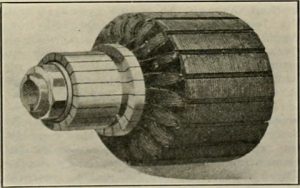
Commutator
A good commutator process takes place when there is no sparking at the brush contacts. Poor commutator process occurs due to the sparking between the brushes and commutator segments. Due to this, there is a possibility of damage when operated continuously.
Commutation in DC Machines
As the coil is rotated in the magnetic field, it cuts the magnetic lines of forces to induce EMF. This induced emf develops current in the winding which is found by using the Flemings’ right-hand rule. The direction of current in the coil changes every cycle in any machine. This direction of the current is changed by using commutator segments. So, a commutator is employed in DC machines to change the direction of the current. The process of a commutator within DC machines is illustrated below.
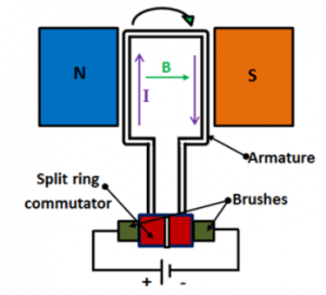
Commutation
Mechanical Reasons for Failure
- Unequal commutator surface
There will be arc production continuously due to the uneven surface. Due to the continuous arc production, the portion of the commutator segments loses its life expectancy.
- Improper brush pressure
As the brushes are attached to the commutator continuously pressure will be imparted on to the commutator segments. Due to this overheating takes place inside the commutator which decreases the life of the commutator.
- Brushes placed in the holders.
Due to improper holding of brushes, vibrations occur which produces noise. This might also decrease the efficiency and life expectancy.
Electrical Reasons for Failure
- The voltage between adjacent commutator segments Increases.
Due to the increase in voltage between adjacent commutator segments, the dielectric strength of Mica insulation gets damaged. This could also lead to the short-circuit of coils.
- Current density at the trailing end of the brush increases.
Due to the increase in current density, the surrounding air gets conducted which leads to sparking. Due to the sparking, the efficiency and life expectancy both will be decreased.
Please refer to this link to know more about DC Generator MCQs
Methods to Improve the Process
These problems arise mainly due to the circulating currents. If we can able to decrease these circulating currents. Then, the commutator operation can be improved. There are different methods to improve commutator operation. They are
- Using the open type of slots
- By using Brush shifting
- By using the resistance method
- Using EMF method
By using Open type slots
By the usage of open type slots, the reluctance path is more such that the strength of leakage flux gets reduced. As reactance voltage is directly proportional to the leakage flux. As the leakage flux is reduced, the reactance voltage also gets reduced.
Vr = N . dФ/DT
ICir = Vr/RB + Rc
The reactance voltage (Vr ) is directly proportional to the circulating currents (ICir ). As the reactance voltage gets reduced, the circulating currents also will be reduced. Thus, this way we can improve the process of the commutator.
By using Brush shifting
Due to the armature reaction, there will be a demagnetization effect of the magnetic field. The magnetic field is distorted due to the armature reaction. This affects the commutator segments and brushes, as they are aligned at no voltage position. Due to the demagnetization, some voltage flows in the commutator at no-load condition. This affects the life of commutator segments and brushes. To avoid these problems, the brush axis is shifted.
By using Resistance Method
By increasing the resistance of the brushes also we can decrease the circulating currents. The equation for the circulating currents is given as
ICir = Vr/RB + Rc
By replacing the low resistance carbon brushes with the high resistance carbon brushes we can decrease the circulating currents. Thus, by decreasing the circulating currents we can improve the commutator operation of a DC generator.
By using the EMF method
We knew that by decreasing the reactance voltage we can decrease the circulating currents.
ICir = Vr/RB + Rc
Emf commutator operation is attained by the addition of Interpol’s or commutating poles. The strength of Interpol’s is about 120% to 130% of cross magnetizing the magnetic field.
ICir = Vr – Ed due to Interpoles/RB + Rc
Thus, due to the Interpol’s, the reactance voltage reduces and further the circulating currents also get reduced. Thus, this is another way to improve the commutator operation.
Therefore, this article discusses brief information what is commutation. It is the process of conversion of the alternating power to direct power or direct power to alternating power in any machine. Apart from commutator operation, we had also studied the reasons for the failure of commutator operation (I,e both mechanical and electrical failures), different methods followed to improve commutator operation. Here is a question for you, how the operation of a commutator takes place in DC machines?
Leave a Reply