An electrical generator is one kind of machine, used to alter energy from supplied mechanical form to electrical form. There are different kinds of generators available in the market and the classification of generators can be done depending on the output received. The output of any machine is AC or alternating current whether it is direct current (DC) or AC generator. Thus, in DC generator a device is necessary to change the current from alternating to direct. This necessity can be fulfilled by using a commutator. This article gives an overview of what is a commutator segment, its meaning, working, diagram, usage in DC machine, split ring, & its applications.
What is Commutator?
It is also called a split-ring commutator. The split rings are made of phosphorous bronze and it is a device connected with the armature core. It is used to collect the current from the armature winding. It changes the form of AC to DC or DC to AC depending upon the requirement. The figure that depicts the cross-sectional view is shown below.
Cross-sectional View
It consists of some segments which are arranged in series to which the ends of armature winding are connected. These divided segments are termed as the commutator segments. These segments are laminated by a thin layer of Mica with a thickness of 0.6 to 0.8mm. The dielectric strength of these segments is nearly 30V to 40V. The segments are made of hard drawn copper of high conductivity. Each segment consists of two coil sides (as one coil contains two coil sides).
The number of these segments is equal to the number of coils.
It is attached to the brush which is used to collect the current from the segments. The segments are the rotating part whereas the brushes are the stationary part.
The function of the Commutator Segment
It is a device that converts either AC to DC or DC to AC I,e it can act as both “Rectifier” or as an “Inverter” depending upon the requirement.
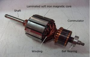
Armature
In the DC generator, at Θ = 0° the induced emf (Ed ) will be zero, at Θ = 90° the induced emf (Ed ) will be maximum, at Θ = 180° induced emf (Ed )is zero, and at Θ = 270° the induced emf (Ed ) will be maximum.
At Θ = 0°, the coil will be in parallel with the magnetic lines of forces. So, no emf will be induced in the winding.
At Θ = 90°, the coil will be perpendicular to the direction of the magnetic lines of forces. The coil now cuts these lines of forces and an emf will be induced as stated by the faradays law of electromagnetic Induction. The figure which explains the movement of the coil in the magnetic field at Θ = 90° is depicted in the following image.
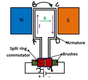
Working at 90 degrees
At Θ = 180°, the coil will be in parallel with the magnetic lines of forces. So, no emf will be induced in the winding.
At Θ = 270°, the coil will be perpendicular to the direction of the magnetic lines of forces. The coil now cuts these lines of forces and an emf will be induced as stated by the faradays law of electromagnetic Induction. The figure which explains the movement of the coil in the magnetic field at Θ = 270° is displayed in the following figure.
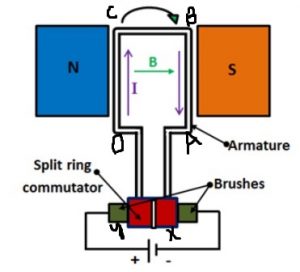
Working at 270 degrees
This process repeats as the coil is rotated inside the magnetic field.
Any machine that is with a heteropolar system generates AC only. AC generator generates AC, DC generator also generates AC. Therefore, any generator with a heteropolar system generates AC only.
Generated e.m.f by any machine initially shown as the following waveform.
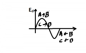
AC Waveform generated Initially
So, initially, the generated power will be alternating in any machine that is converted to DC. The waveform after conversion i,e the AC is changed to DC can be illustrated like the following diagram.
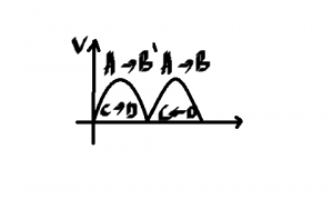
Waveform after Conversion
The generated emf frequency of DC generator or AC generator is given as
f = PN/120
where,
f = frequency of the system,
N = speed in r.p.m, and
P = number of poles.
In the DC generator, the segments convert the generated AC to DC and hence, it acts as a “full-wave uncontrolled mechanical Rectifier”.
In DC Motor, the segments convert the generated DC to AC and hence, it acts as a “full-wave uncontrolled mechanical Inverter”.
Importance of the Commutator
The difference between the AC generator and the DC generator exists in the segments. In the DC machine, the field winding is employed on the stator and armature winding is employed on the rotor to facilitate the commutation process.In the case of the AC machine, the armature winding is placed on the stator and field winding can be arranged on the rotor. The stationary armature winding is more advantageous compared to the rotating armature winding. In the DC machine, whenever the armature winding is located on the rotor, then it requires more winding as well as the number of brushes. Due to the increase in the number of brushes, sparking increases at the brushes which decrease efficiency. So, the stationary armature is more advantageous compared to the rotating armature.
The AC generator is comprised of the combination of the slip rings and brush whereas the DC generator is comprised of the combination of the commutator and brush.
Applications
- Used in DC generator and motor, Ac generator, and motor, and in universal motors
Thus, this article covers an overview of a commutator which includes some segments that are used for the changing AC to DC otherwise DC to AC. And also, we discussed commutation in DC generators, and its importance, different techniques to enhance commutation as well as its applications. Here is a question for you, what is the main role of a commutator in a Universal motor?
Leave a Reply