All voltage sources cannot provide stable output because of fluctuations within the circuit. For obtaining stable output, the voltage regulator is implemented. A voltage regulator is used to create and maintain a stable output voltage which is used for DC/DC power conversion, some can perform AC/DC or AC/AC power conversion. The integrated circuits or ICs which are used for voltage regulation are known as voltage regulator ICs. There are different types of voltage regulator ICs like 7805 IC, 7812 IC, TL783, 7800, 7812, and many more. So this article discusses one of the types of voltage regulators namely the 7805 voltage regulator.
What is a 7805 Voltage Regulator?
The 7805 voltage regulator is a fixed linear voltage regulator IC and it is a member of the family of 78xx series of voltage regulator IC. In 7805 IC, 78 is a positive voltage regulator whereas 05 is the output voltage. The input voltage of this voltage regulator is up to 35V.
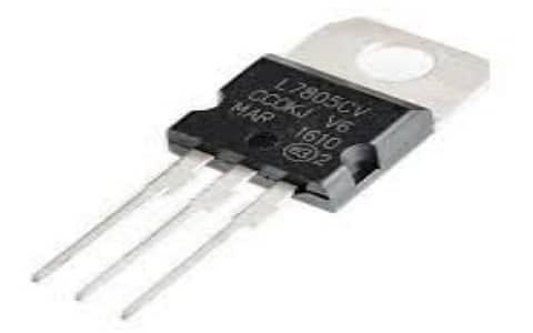
7805 Voltage Regulator
Pin Configuration:
The 7805 voltage regulator includes three pins. The pin configuration of the 7805 voltage regulator is shown below where each pin and its functionality are discussed below.
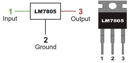
7805 IC Pin Configuration
- Pin1 (Input Pin): This pin is used to provide input voltage which ranges from 7V to 35V. For regulation, an unregulated voltage is applied to this pin.
- Pin2 (GND Pin): This is a GND pin that is equally neutral for input and output.
- Pin3 (Output Pin): This is an output pin that provides 5V output.
Features & Specifications:
The features and specifications of the 7805 voltage regulator include the following.
- It is a 3 terminal integrated circuit.
- Its output current is up to 1.5A.
- It has thermal overload protection internally.
- It has a high power dissipation capacity.
- Short circuit current limiting internally.
The minimum input voltage is 7V. - The maximum input voltage is 25V.
- The operating current is 5mA
- The maximum junction temperature is 125 degrees Celsius
- Available in KTE, TO-220, SOT-223, TO-92, and TO-3 packages.
- The equivalent 7805 voltage regulators are; LM340, LM340A & LM1084-5.0 can be used as the equivalent to LM7805; If these ICs are not available then LM317 IC can be used to obtain stable output voltage like 5V.
7805 Voltage Regulator Circuit
The circuit diagram of the 7805 voltage regulator is shown below which is used to provide a regulated voltage like 5V from the AC Mains supply. The required components to male this circuit mainly include a step-down transformer, a bridge rectifier including 4 1N4007 diodes, 1A fuse, and capacitors – 0.22μF, 0.1μF & 1000μF, 1N4007 diode, and 7805 IC.
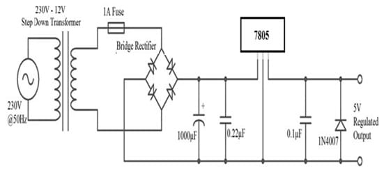
7805 Voltage Regulator Circuit
7805 Voltage Regulator Working
This circuit is very helpful in converting the AC power supply first from mains into unregulated DC and after that converts into a constant regulated DC. This circuit can be made with different components which are mentioned above.
First, the above circuit can be divided into two main parts. So in the primary part, the AC mains supply can be changed into unregulated DC. In the next part, the unregulated DC can be changed into a regulated 5V DC.
At first, a step-down transformer is used where its primary winding is connected to the main supply and the secondary winding is connected to Bridge rectifier. Here, a 1A fuse can be arranged in between the step-down transformer & the bridge rectifier. So this will limit the flow of current drawn through the circuit to 1A.
From the bridge rectifier, the rectified DC can be smoothened out by using a 1000μF Capacitor. As a result, the output voltage across the 1000μF capacitor is 12V DC. So this voltage can be given as an input to the 7805 IC. After that, this voltage can be converted into 5V regulated DC. Finally, the output voltage can be attained at its output terminals as 5V.
Heat Dissipation in IC 7805
The heat dissipation in the 7805 voltage regulator IC is very high within the heat form. This heat can be occurred because of the difference in the input and output voltage values. So, if the difference value between input voltage & output voltage is maximum, then heat generation will be more. So a heat sink is used to avoid malfunction.
The least amount of tolerable difference among the input & output voltage to maintain the output voltage at the correct level is known as dropout voltage. So the input voltage has to maintain 2V to 3V above the output voltage, otherwise, an appropriate heat sink must be connected to dissipate surplus heat. To calculate the size of the heat sink properly, the below formula is used.
Generated heat = Input voltage X output current
To analyze the main relation of heat generated as well as the value of input voltage within this voltage regulator, the following two examples are given.
A system including 12V input voltage and output current necessary is 0.6A. So heat produced
(12-5) x 0.6 = 4.2W.
So, heat energy wasted is 4.2 W & the actual used energy
V x I = 5 x 0.6 = 3.0 W
That is nearly double energy is exhausted as heat.
After that, we can consider the case once the input voltage is lesser like 7V.
So in this case, the generated heat is;
(7-5) x 0.6 = 1.2W
So finally we can conclude that; for maximum input voltage, the voltage regulator IC will turn highly ineffective.
The important points need to consider while using this 7805 voltage regulator. The first point is the input voltage must be high always as compared to the output voltage. The input and output currents are identical almost which means; if the input current is 7.5V 1A then the output current will be 5V 1A because the remaining power will be dissipated like heat. So a heat sink has to use with this voltage regulator.
Important Factors while Selecting a Voltage Regulator
The selection of any voltage regulator can be done based on different factors like input & output voltage, drop-out voltage, efficiency, dissipation of power, the accuracy of voltage, load regulation, and line regulation.
Input & Output Voltage
Knowing input and output voltage for voltage regulators is very important. The input voltage used by linear voltage regulators is higher compared to the rated o/p voltage. So, if the input voltage (Vin) is less than the preferred output voltage, then it is known as an insufficient voltage which causes the voltage regulator to fall out & supplies unregulated output.
Dropout Voltage
The dissimilarity between input & output voltages of the regulator is known as dropout voltage. For instance; if the input voltage of the 7805 regulators is 6V & the o/p voltage is 3V then the dropout voltage will be 3V. If the input voltage of the regulator goes below, then both the output voltage & the dropout voltage will affect in an unregulated output that can harm your device. So checking the dropout voltage is mandatory when selecting a voltage regulator.
Power Dissipation
As compared to switching voltage regulators, these linear voltage regulators dissipate more power. So, extreme power dissipation can result in battery overheating, draining, or harm to the device. So, calculating the power dissipation for the voltage regulator is necessary by using the following formula.
Power (P) = (Input Voltage (Vin) – Output Voltage (Vout)) x Current (I)
To avoid the power dissipation, you can utilize the switching voltage regulator in place of the linear voltage regulator.
Efficiency
The efficiency of the voltage regulator can be defined as the ratio of o/p power & i/p power. So the efficiency of these regulators is directly restricted through the quiescent current & dropout voltage because if the dropout voltage is high then the efficiency will be low. For maximum efficiency, both the quiescent current & drop-out voltage should be reduced, and the voltage dissimilarity between input and output should be reduced.
Load Regulation
Load regulation can be defined as the capacity of the circuit to maintain a particular output voltage below unreliable load conditions. So it is expressed as
Load Regulation = ∆Vout/ ∆Iout
Line Regulation
Line regulation can be defined as the capacity of the circuit to maintain the particular output voltage through the unreliable input voltage. So this can be expressed as;
Line Regulation = ∆Vout / ∆Vin
So for choosing a proper voltage regulator IC for any application, all the above factors must be considered.
Advantages
The advantages of the 7805 voltage regulator IC include the following.
- This voltage regulator IC is used easily for local regulation.
- This IC is reliable, very efficient, and versatile.
- Less cost & easily available because of mass production
- Its size is compact, strong, and lightweight.
- The design of the power supply circuit will become very simple & fast.
- It is simply manufactured including some features like in-built protection, voltage or current boosting, programmable o/p, internal protections, etc.
- Its transient response is fast.
- This voltage regulator does not require any additional component to manage its output voltage.
- This IC includes inbuilt protection for protecting from overvoltage.
- A heat sink is utilized throughout the GND terminal to defend the regulator from short circuits/high currents.
- This regulator includes very less external components.
- It has a high current circuit application capacity.
- These are applicable in lower & higher frequency sensitive circuits like an amplifier.
- It maintains the o/p voltage at a stable value.
Disadvantages
The disadvantages of the 7805 voltage regulator IC include the following.
- This voltage regulator circuit has a least limit within its input voltage approximately 2.5v as compared to the o/p voltage.
- This circuit is heavier as compared to switching circuits.
- The circuit efficiency is lower because of power dissipation through heat.
- The 7800 series voltage regulators are not new, so at present, these ICs are not frequently used.
- As compared to SMPS, they provide a low efficiency.
Applications of 7805 Voltage Regulator
The applications of the 7805 voltage regulator IC include the following.
- Regulated dual supply.
- Current regulator.
- These regulators are used to design different circuits like UPS, Phone chargers, portable CD players, etc
- This regulator is used in different circuits like Fixed & adjustable output regulators, Phone chargers, bench power supplies, current regulators,
- Inductance meters & reversal protection circuits.
- This voltage regulator gives +5v constant output voltage, so this will be suitable for sensors, Arduino boards & microcontrollers.
- This regulator can be used as an adjustable output regulator.
- This regulator functions as a dual power supply.
Thus, this is all about an overview of the 7805 voltage regulator – working with applications. So the factors which are discussed above when selecting a voltage regulator will enhance the reliability and also its lifetime. Here is a question for you, what is scaling the output?