DC to DC Converter
There are various types of power electronic converters which are frequently used in electric power system applications such as power converter, regulated power supply, DC power supply and so on. The power electronics converters can be classified as AC to DC converter or Rectifier, DC to AC converter or Inverter, AC to AC converter, DC to DC converter, and so on. These converters are again classified into different types based on different criteria. If we consider DC to DC converters, these are classified as DC to DC buck converter, DC to DC boost converter, and DC to DC buck-boost converter. Here, we discuss in detail about the DC to DC converters, operating principle and functionality.
DC to DC Converter
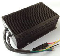
A DC-DC converter is a power electronics device that accepts a DC input voltage and also provides a DC output voltage. The output voltage of DC to DC converter can be greater than the input voltage or vice versa. The converter output voltages are used to match the power supply required to the loads. The connection and disconnection of power supply to the load can be controlled using a switch in the simple DC to DC converter circuit. DC to DC converter circuits consists of a transistor or diode switch, energy storage devices like inductors or capacitors and these converters are generally used as linear voltage regulators or switched mode voltage regulators. DC to DC converters are used to provide DC regulated power supply, constant DC power supply to the electrical and electronics project circuits.
DC to DC Converter Operating Principle and Functionality
To understand the DC to DC converter operating principle and functionality, let us consider the working principle of DC to DC boost converter.
DC to DC Boost Converter
The low input DC voltage is converted into high output DC voltage using DC to DC boost converter. As the input voltage is stepped up compared to output voltage, hence, it is also called as a step up converter. Generally, DC to DC converters can be designed using power semiconductor switching devices and discrete electrical and electronics components.
In DC to DC converter, the converter operates in two modes:
- Continuous Conduction Mode
- Discontinuous Conduction Mode

DC to DC Boost Converter Continuous Conduction Mode Circuit
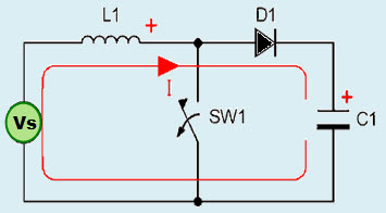
The continuous conduction mode circuit of the DC to DC boost converter is shown in the figure that consists of an inductor, capacitor, switching device, diode, and input voltage source. This boost converter circuit switch is controlled using a pulse width modulator (PWM). If this switch is in ON state, then energy will be developed in the inductor and thus more energy will be delivered to the output.

DC to DC Boost Converter Discontinuous Conduction Mode Circuit
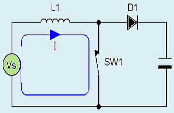
The discontinuous conduction mode circuit of the DC to DC boost converter is shown in the figure that consists of elements such as capacitor, inductor, voltage source, diode, and switching device. In this discontinuous conduction mode, if the switch is in ON state, then energy will be delivered to the power storage element, inductor. If the switch is in OFF state for some period, then the inductor current will reach zero until the next switching cycle is on. Thus, the capacitor gets charged and discharged with respect to the input voltage. But, here the output voltage in discontinuous conduction mode is less than the output voltage in continuous conduction mode.
Similarly, buck converters are used for converting high input DC voltage into low output DC voltage. Buck-boost converters are used for maintaining output DC voltage high or low based on the input DC voltage source. If the input DC voltage is high, then the output will be low and vice-versa. Thus, we can maintain regulated DC voltage using buck-boost converters.
Practical Example of DC to DC Converter
DC 12V to 24V converter can be considered as a practical example of DC to DC converter (boost converter) which is used as DC power supply.
In several instances, we require 24V DC from a 12V source. This circuit suits well enough for converting DC 12v to 24v. This circuit is capable to produce a steady 24C DC output and to deliver output current up to 800mA. The circuit is basically a DC to DC converter designed using LM324 IC which is configured as an oscillator. This LM324 is used for producing the switching frequency and a transistor is used as the semiconductor switching element.
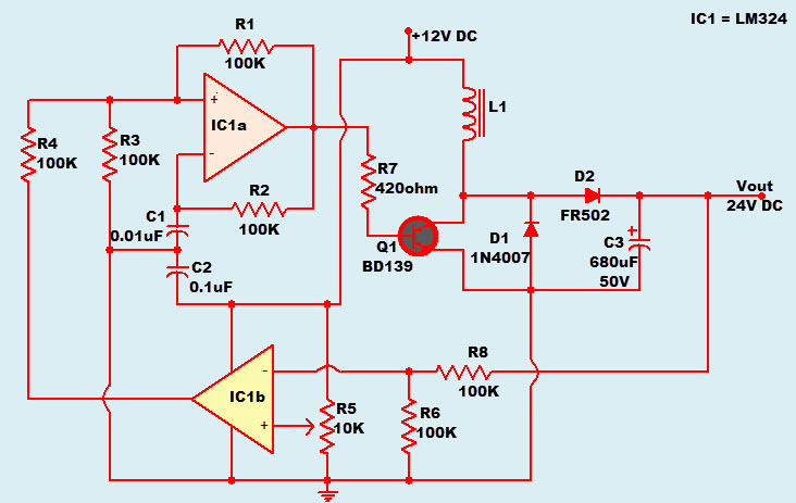
IC LM324 is a major component of this DC to DC converter circuit. LM324 is a quad operational amplifier and out of these four operational amplifiers inside the IC, only two are used in this circuit. An oscillator is formed by the IC1a, R1, R2, R3 and C1, this oscillator operates around 500Hz. By using resistor R2 and capacitor C1 we can set the oscillator frequency. A comparator is formed by IC1b, which is used to compare the output voltage with a reference voltage and such that to control the output voltage this feedback voltage is given to the oscillator stage.

DC 12V to 24V Converter Circuit Diagram
A preset R5 is connected to the non inverting pin of IC1 to form a potential divider circuit. The inverting input pin is connected to the output through a 100K resistor. The output of this IC1b comparator is given to the non inverting input pin of IC1a through another 100K resistor. The output of the oscillator IC1a is given to the base terminal of transistor Q1 through a resistor R7 to limit the transistor Q1 base current.
If the output of the oscillator IC1a is high, then the transistor Q1 switches ON and the current passing through the inductor L1 increases. If the output of oscillator IC1a is low, then the transistor Q1 switches OFF and thus the inductor current passes through D2, C3, and load if any in the circuit. The fly back diode D2 gets forward biased and thus during the ON state the energy is stored in the inductor. This stored energy will be dumped into the capacitor. Diode D1 acts as a freewheeling diode.
We know that, according to the property of an inductor, it always tries to oppose sudden variation in the current passing through it. With this property of the inductor, when the inductor is charged it stores energy and when the inductor is discharged it acts like an energy source. The voltage it delivers during the discharge is proportional to the rate of change of current through it. If the switching frequency increases, then the induced emf from the inductor also increases.
know more about Voltage to Current Converter MCQs.
For more information about power converters and power electronics projects, feel free to contact us by posting your comments in the comments section below.