As we all know how crucial electronic circuits are in use these days. We can say that the entire scope of software, industrial, engineering, medical and agricultural industries are either in the way connected to these electrical circuits. So, moving in this scenario, rectifiers are the circuits that appeared as the most common electronic power supplies. As many circuits need DC power source to power up many electric components. So, the device which holds good for this operation is a “Rectifier”. So, let’s discuss the concept of what a bridge rectifier is, its circuit and what is its operation?
What is a Bridge Rectifier?
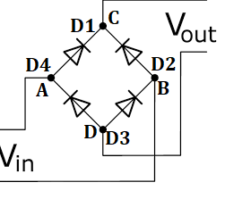
The one special circuit which produces a similar output as that of a full-wave rectifier is Bridge Rectifier where this circuit uses four diodes to form a closed loop. With the help of these diodes, alternating current is transformed as direct current. The delivered output holds a similar polarity not depending on the given input. The selection of bridge rectifiers is based on multiple parameters like power levels, breakdown voltage, temperature ranges, and others. The benefit behind this circuit is that there is no necessity of center-tapped transformer and so the price is minimum and even the size is small, where one side of the bridge loop is connected to the secondary winding and the other side is connected to load. The below diagram shows the bridge rectifier circuit
bridge-rectifier
Bridge Rectifier Circuit Diagram and Construction
As we have already discussed the uniqueness of this circuit is its connected loop through four diodes named D1, D2, D3, and D4 along with a load resistor named RL. The formed loop holds the enhanced efficiency to transform AC into DC current. The given AC wave is fed into across A and B terminals and the output signal which is in DC form is received across RL and it is across C and D.
Bridge Rectifier Working
The four diodes are in series connection and this allows only two of the diode to pass electric current for each half cycle. For the positive half cycle, D1 and D3 allow electric current whereas during negative half cycle D2 and D4 allow electric current through them. This means that at the time of the positive half cycle, D1 and D3 are in forwarding biased condition and D2 and D4 are in reverse biased condition.
So, current flow will be across the path created by D1 and D3 and the output voltage is positive across C and D. In the same way when a negative pulse is applied, D1 and D3 are in reverse biased condition and D2 and D4 are in forward biased condition. So, the current flow will be across the path created by D2 and D4 and the output voltage is positive across C and D.
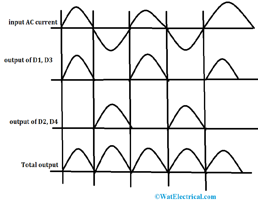
The point that has to be noted here that the output voltage is of positive polarity irrespective of the applied input polarity. But the received output will be in pulsating and this can be removed by using a capacitor in the construction of the circuit. So, this is the bridge rectifier operation. The output waveforms are shown below:
waveforms-of-bridge-rectifier
The Efficiency of Bridge Rectifier
Rectifier efficiency corresponds to know the performance of the bridge rectifier which means that how effectively AC voltage gets transformed into DC voltage. High efficiency indicates that that rectifier performs well whereas low efficiency indicates low performance. It is denoted as the ratio of DC output to the corresponding AC input. It is represented with ‘ŋ’.
Where ŋ = DC output/AC input = PD/PA
The maximum efficiency of the rectifier is 81.1%.
Types of Bridge Rectifiers
There are various classifications of bridge rectifiers and these classifications are based on parameters like circuit configuration, handling ability, supply kind and many. The basic classification is a single-phase and three-phase rectifiers where this is based on the kind of input work. Let’s have a brief discussion of the classification.
Single Phase and Three Phase Rectifiers
The name itself almost defines the type of rectifier it is. When the applied input in of single-phase, it is termed as a single-phase rectifier whereas when the applied input is of three phases, it is termed as a three-phase rectifier. The initial one is constructed with 4 diodes where the three-phase type has 6 diodes to generate the DC voltage. Further, these are classified as an uncontrolled and controlled type based on the switching equipment like that of thyristors and diodes.
Controlled Bridge Rectifier
These are again categorized as controlled half-wave and full-wave rectifiers. The name defines that the output voltage can be modified. As there are few flaws in the uncontrolled bridge rectifier, controlled ones can eliminate those. This rectifier is constructed with MOSFET, IGBT, and silicon-controlled resistors. This means one can have complete control when SCRs can be switched across ON and OFF conditions depending on the applied gate pulses. It is because when SCR is forward bias conduction, it will conduct electricity and in reverse condition, it blocks the current. So, there will be a controlled output.
Again, these are of half-wave and full-wave controlled center-tap and bridge rectifiers.
Uncontrolled Bridge Rectifier
The name defines that the output voltage cannot be modified. This rectifier is constructed with switches and these are of controllable and uncontrollable switches. As diode allows a flow of current only in single. The operation of the diode is not restricted until it is reverse biased. So, with the combination of diodes and rectifiers, there will be no control for the operation and so these are named uncontrollable bridge rectifiers. Based on the load necessity, these will not allow power variation.
Again, these are of half-wave and full-wave uncontrolled, center-tap and bridge rectifiers.
Ripple Factor
The ripple factor of the bridge rectifier is defined as the smoothness level of the generated DC output. The signal which has fewer ripples has maximum ripple factor and smooth whereas the signal that has more ripples has minimum ripple factor and pulsating.
It is represented as the ratio of ripple voltage level to that of DC voltage.
It is given by
γ = sqrt [(Vrms/vDC)2 -1]
Advantages
The advantages of bridge rectifier are stated as follows:
- When compared with a half-wave rectifier, the output signal is less pulsating and has more smoothness. This means it has a maximum ripple factor.
- Enhanced rectifier efficiency
- Minimal loss of power and space as the circuit is of an only resistor, diodes, and input source
Applications
In general, because of the rectification, rectifiers are employed in power rectification and many electronic devices.
The applications of bridge rectifier are as below:
- Used for the conversion of AC to DC voltages
- To generate polarized voltages, these are implemented in electric welding’s
- Employed in rolling stock, toehold and three-phase motors for the operation of trains
- Mostly bridge rectifiers are applied in modulations, multipliers and demodulation equipment.
- Used for signal peak detection services and in AM radios too.
FAQs
1). How does the current flow in a bridge rectifier?
For the negative and positive half-cycles, the current flow will be in a forward path across the loop.
2). Is a bridge rectifier a full-wave rectifier?
It is considered as a kind of full-wave rectifier which holds the efficiency to convert AC input to DC output.
3). Why do we use 4 diodes in the bridge rectifier?
Without the necessity of a center-tapped transformer, the usage of four diodes allows for complete rectification.
4). Which diode is used in the bridge rectifier?
Most of the bridge rectifiers employ silicon diodes where because there will be less voltage drop and also produces maximum output.
5). Why the capacitor is used in the bridge rectifier?
To remove any kind of pulsating waves, present in the DC signal, capacitors are employed in the construction of bridge rectifiers.
Know more about AC Bridge MCQs, Silicon Controlled Rectifiers MCQs.
This is all about the detailed concept of a bridge rectifier. The uniqueness of construction allows this device to be employed in various kinds of industries and devices. So, learn more concepts of bridge rectifiers and know what is the exact functionality and how it operates?