An electrical isolator which is commonly known as an isolator or disconnector is a piece of equipment that is used in electric devices and power systems with the main function of effectively isolating two different parts of an instrument. By definition, isolation is the process of complete separation of various parts of an apparatus and this separation can either be physical or electrical, or both.
As already discussed the main purpose of an isolator is safety because if a fault occurs in one section of a circuit or power supply then an electrical isolator is used as a switch to keep apart that section from other sections of the system to perform repair work. In a similar scenario, isolators also ensure the safety of workers in regular maintenance and service of the power system. Isolators separate a certain circuit from the electricity mains and discharge any residual current, left in the circuit, to the ground.
What is an Electrical Isolator?
Definition: Isolators are also called disconnect switches which operate under no-load conditions. They are not manufactured for any making or breaking current capacity. They don’t have an arc quenching system within it. Its main use in the electrical system is to disconnect a particular part after the current interruption from that particular part. They ensure there is no current in the circuit until everything is in order. They are placed on each side of the circuit breaker to provide isolation. Generally, an automatic type is preferred.

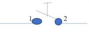
isolator-symbol
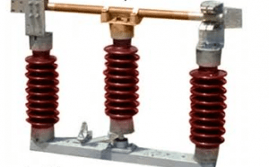
Isolator Switch
These switches are generally used for the repair or replacement of a circuit breaker. It acts as a switch that disconnects the required part from the circuit where the repair has to be done. It does not have any current ratings as compared to CB as these are operated with current being made zero in the circuit. These switches cannot be opened unless CB is open and CB cannot be closed unless the isolator is closed.

isolator
Electrical Isolator Working Principle
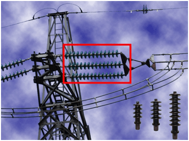
The working of an isolator is very simple and it can be operated in various ways such as fully automatic, semi-automatic, or manually operated. Isolators are sometimes used as switches that can be opened or closed based on the requirement. But many times, isolators are used permanently in a fixed position to keep isolation such as in electrical transmission lines, transformers, and grid stations as shown in the figure below.

This figure shows isolators being used as insulators in transmission lines to isolate transmission towers from the conductor. And here isolators are particularly useful in eliminating grounding loops, such as lowering the risk of accidental paths for electric current to flow towards the ground.
Isolator switches, in particular, are used in power grids and substations to efficiently isolate very high voltage apparatuses such as transformers and circuit-breakers when they are due for maintenance. Commonly used isolators are not intended to stop current during a fault to eliminate high voltage arcs, which occur due to disturbance in electric conductors. In high-voltage power systems, isolators are used in conjunction with circuit breakers to provide an extra layer of safety.
A first circuit breaker is opened which disconnects the circuit then the isolator is also opened. And for the reverse process, the first isolator is closed then the circuit breaker is closed and the circuit is reconnected. The picture below shows the isolators in a disconnected state within a power substation. It can be seen that it is a physical and mechanical system. And It can be operated manually or it can be actuated automatically.
Types of Electrical Isolators
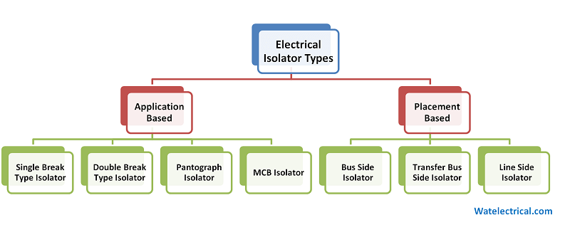
There are various kinds of isolators available in the market. Choice of electrical isolators depends upon the requirement and application and based on the placement in the system. Isolators based on Application can be classified into four types.
- Single Break Isolator
- Double Break Isolator
- Pantograph Isolator
- MCB Isolator

Depending upon the position in the power system, the Isolators can further be categorized into the following three types according to their placement in the power system.
- Bus side isolator: It directly connects to the main bus
- Transfer bus side isolator: It directly connects to the transfer bus.
- Lineside isolator: It is generally located at the line side of the feeder
In a single break isolator, only one terminal connects and disconnects whereas in a double break isolator both terminals at each side connect and disconnect because the central terminal is moveable. In a pantograph type isolator, both terminals at each side connect and disconnect only because of the forces of stress or tension, and usually is no locking mechanism.
This type of pantograph isolator is widely used in electric trains to obtain electricity from overhead transmission lines. Miniature circuit breaker (MCB) as apparent from the name is designed for low power requirements such as homes and offices. It is designed in small compact cases so that it can be used in domestic scale wiring systems. Horizontal double break isolator in substations use is abundant.
Isolators are generally used on both sides of the circuit breaker, this measure is taken just to ensure extra safety and protection because in a power system incoming and outgoing lines can have multiple sources of power, and disconnecting one side is sometimes not enough. So, the isolator on both sides of the circuit breaker allows essential replacement and services requirements to be performed safely.
Depending on their Position
- Bus Side Isolator: These are connected to the main buses in the substation. Whenever there is a need for repair or replacement of any bus, they are operated.
- Lineside Isolator: These are connected between the line and any feeder. A feeder is a line that carries power from the Substation to the distribution system.
- Transfer Bus Side Isolator: In an electrical system for reliability main or transfer bus is used. In case the main bus side isolator is unavailable due to some fault/maintenance transfer bus isolator is used. These are used in combination with a circuit breaker.
Depending on Line Voltage
- Low Voltage: These isolators are designed to withstand voltage up to 11KV
- Medium Voltage: Isolators for voltages between 11KV to 66KV come under this type.
- High Voltage: Isolators for voltages between 66KV to 330KV come under this category and they have a high withstanding capacity.
Difference between Electrical Isolator and Circuit Breaker
A major question arises in mind that why isolator is used on both sides of the circuit breaker? The isolator is designed to work when there is no load connected which makes it an off-loading device. Whereas circuit-breaker is considered an on-load device. Both of these devices have the common purpose of disconnecting a certain section of the circuit from the rest of the system. A circuit breaker is an electronic device made up of solid-state components like MOSFETs and BJTs whereas an isolator is a mechanical equipment and it works as a switch.
Does a question arise that what is the point of using an isolator when it cannot even be used under load whereas circuit-breaker trips automatically under fault? The answer to this question is quite straightforward. When circuit breaker trips due to a certain fault then we cannot make sure whether or not a faulty area is completely isolated because circuit-breakers are mostly installed remotely. To make sure that a system is completely isolated, a physical and mechanical on-site isolation system is used. Isolators have an overall lower capacity of withstanding current and voltage relative to the circuit breakers.
Applications of Electrical Isolator
The applications of isolator include the following.
The main purpose is to disconnect or de-energize the circuit completely and for this purpose, they are used in substations, power generating stations, and signal isolation. It provides more safety for the operator as it ensures the total disconnection of the electrical system. It is provided before and after the circuit breaker in high voltage systems. First, the circuit breaker operates then operates such that the equipment, busbars, and transformers are safe.
- High Voltage Devices: Isolators are used in High Voltage devices.
- Isolator in Substation: When a fault occurs in a substation, the isolator cuts out a portion of a substation.
- Signal Isolation: Isolators can be used for the isolation of signals.
Isolator in Microwave
Isolator at microwave level is a two-port device that permits transmission of microwave power in only one direction. It is specifically useful for protecting input and output equipment from affecting each other. Isolatorsplay a crucial role in minimizing the interference between incident and reflected waves, and they also allow a constant impedance at the transmitter which in turn maximizes the power transfer.
They usually are made up of magnets or ferrite materials. When choosing a microwave isolator, it is necessary to select a component with the least insertion loss so that isolator itself doesn’t introduce a lot of noise into the system.
Isolator in Substation
Depending on the voltage in the substation, isolators of that voltage level is used. They are used to disconnect the transformers, circuit breakers, and bus bars for repair and maintenance. As mentioned before, they are operated under no current conditions (no load) only since they don’t have rated making or breaking current capacity.
Please refer to this link for Electrical Wiring MCQs, Isolator MCQs, Circuit Breaker MCQs.
We have covered in detail What is an Isolator, the Working principle and its functioning along with the Types of Electrical Isolators, the Main differences between an Isolator and a Circuit breaker along the major applications of an Electrical Isolator. To summarize the characteristics of an isolator include the following, it is used as an electrical offload device, manually operated, De-energizes the circuit, helps insecure maintenance by isolation, etc. Here is a question for you what is the difference between an Isolator and an MCB?