 In the recent years, advancements in discrete semiconductors with high-performance and low-cost integrated circuits (ICs) led to the design active power factor correction over a several range of applications. Mostly, these APFC panes are introduced in many of the industries for better utilization of available power supply. Good or high-power factor results in efficient electricity consumption and thus reduces electricity bills.
What is Power Factor?
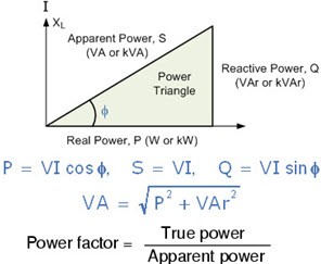
Power factor is defined as the ratio of a real power to the apparent power. And also, it is the cosine angle between the voltage and current. The real power ‘P’ is the average of instantaneous voltage and current product over a cycle during which some useful work in the equipments is done. Whereas, the apparent power ‘S’ is the RMS value of the voltage and current’s product, which is the total power available, as shown in the figure.

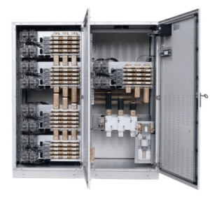
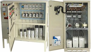
Power Factor correction Panel
The below equation tells that over an available apparent power how much is the true power accounts. The power factor measures the amount of energy used for a given supply from the utility company. Imagine, if the power factor is 0.6, which means, only 60 percent of the power is utilized for a given 100 percent power, and the remaining power is considered as waste or lost.

Power Factor
If both the voltage and current are in phase in nature, then the power factor is 1, but if these are not in phase, the power factor will vary. This variation of phase difference is due to the type of loads: resistive, inductive, capacitive and other non linear loads.
Why Power Factor Correction Is Needed?
Most of the industrial loads are inductive in nature, i.e., lagging loads, so the power factor is low or very poor that depends on the capacity of the reactive power. These reactive loads include electric motors, induction heaters, furnaces, lamp ballast, etc. These loads cause the currents to lag the voltages with some angle resulting in poor power factor.
This low power factor draws high internal current which in turn creates excessive heat in the equipments, huge voltage drop offs and poor voltage regulation. Low-power factor requires larger KVA rating for the equipments, so the cost of the equipments increases. The main aspect is that a power supply company imposes a penalty for the low-power factor in the electricity bills.
Keeping the above things in mind, one can say that the power factor must be corrected for a better utilization of the power, and to overcome all the drawbacks discussed above.
How Power Factor Is Corrected?
Since a low-power factor results in purchasing more power to obtain the same load kW, while a high-power factor leads to a maximum use of electrical power. This suggests that the power factor correction is needed. This can be done with the capacitors possessing electronic circuitry with which they can decrease the lagging angle between the voltages and currents. Switched capacitors method is widely recognized method of minimizing the losses through a reactive power consumption.
In many industries, larger APFC panels are installed in parallel to the loads wherein a set of capacitors are switched-on prior to correcting the power factor. PFC panels designs depend on the end application requirements and prominent driving factors.
So far you might have got a better idea and understanding of the power factor and its correction for efficient usage of power. In order to make you understand the concept of improving power factor better, the following real-time application based circuit is quite helpful.
Minimizing Penalty in Industrial Power Consumption by Engaging APFC Unit
This proposed project improves a system’s power factor by using a set of capacitors that are connected in parallel with the inductive load. In this system, a temporary lagging load is created with the use of inductor choke, which is used in many tube lights to build high voltage. In all four capacitors, the insertion to load depends on the value of the power factor. Imagine, if the power factor is below 0.5, then there will be a chance to join all the capacitor to the load.
This system is implemented by the concepts of Zero Voltage Switching (ZVS) and Zero Current Switching (ZCS). The voltage’s and current’s zero positions are detected by this circuit, which calculates the time difference between these two, and correspondingly calculates the power factor. Therefore, depending on this value of the power factor, the capacitors are switched.
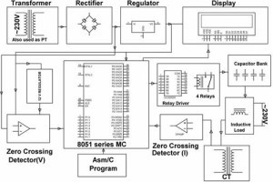
A microcontroller is used in this project as a central processing unit to calculate the power factor and to switch the capacitors. The working of this project is explained with the help of the below block diagram, which consists of a power supply block to power the entire circuit, a voltage and a current zero crossing detection block, in addition to the load arrangement with the capacitors that are switched on by using relays.

Block diagram of Minimizing Penalty in Industrial Power Consumption by Engaging APFC Unit
It uses a potential transformer to supply the voltage to the Zero Voltage Crossing circuit, which detects the zero crossing of the voltage wave form, for every 10 ms – by comparing the voltage pulses applied to the operational amplifier. These voltage pulses from the operational amplifier are applied to the microcontroller as interrupt signals.
Similarly, a current transformer is used here to give the current wave to the ZCS circuit wherein the operational amplifier output is enabled for every 10 ms by comparing the zero position of the current with the predefined setting. This signal is also applied to the microcontroller as an interrupt signal. The microcontroller finds time elapse between these two interrupts and substitutes it in a certain equation for calculating the power factor.
If this power factor value is in between 0.95 to 1, then the microcontroller doesn’t send any command signals to the relay driver to switch the capacitors on. But, if it is less than 0.95, then the microcontroller sends command signals to the relay driver so that the capacitor comes in parallel with the load. Therefore, these capacitors reduce the lagging nature of the load by giving leading currents to it. The number of capacitors’ switching depends on the value of the power factor – very low power factor needs all the capacitor, whereas high power factor needs none of those.
In this way, one can improve the lagging power factor so that the losses will be minimized and therefore, the penalty imposed by the power supply companies will be minimized. We hope that you have got a better understanding of this power factor correction concept with the above application-oriented example. Therefore, you as a reader can share your doubts, comments and suggestions in the comment section and also can contact us for any help regarding any project or similar sort of projects.
Photo Credits
- Power Factor diagram by dnatechindia