Till the 17th century, there were no centrifugal pumps, but you might wonder how people used to transfer liquids. Before the invention of centrifugal pumps, there were mud lifting machines which were almost in portrayal to that of these pumps. But, few of the complications in mud lifting machines turned people’s attraction towards the implementation of centrifugal pumps. Centrifugal pumps are considered as the archetype of process pump spares applied with centrifugal force. So, let’s get a clear insight into what is a centrifugal pump, its working, components, and applications.
What is Centrifugal Pump?
The exact centrifugal pump definition goes here, it is the most prominent pumping device utilized for fluid transfers. To be clear, it can be stated as a pump that makes use of a revolving impeller providing fluid movement through centrifugal force. These are accurate pumping devices employed mostly for fluid transmission from one location to the other location across numerous domains. These tools are more valuable as they manage huge amounts of fluid transmissions, allow extensive high flow rates and holds the capability to adapt their flow rates as per the desired range.

centrifugal-pump
Centrifugal pumps are usually manufactured to be appropriate for liquids having moderately minimal viscosity levels like that of graded oils or water. Heavy viscosity liquids like 10 -20 wt oils operating at 68- 700F need extra horsepower for the centrifugal pump’s operation.
Centrifugal Pump Working
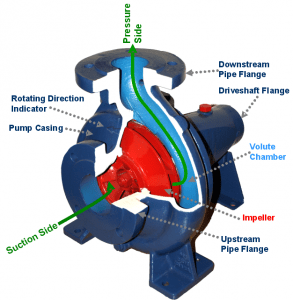
Centrifugal pumps are mainly used to fuel up the liquid levels from low to high. These devices operate on a very basic mechanism whereby the conversion of the motor’s rotational energy to that of the energy of what a fluid has. The two crucial components of the centrifugal pump responsible for energy conversion are casing and impeller. So, the centrifugal pump working principle is that the impeller is the revolving component of the pump and the casing section corresponds to a sealed passage that encloses the impeller.
In this pumping system, the fluid moves into the casing section fall down on the impeller blades at the impeller eye position and rotate both diagonally and tangentially to the external side till it moves from the impeller to the diffusion section of the casing. When the fluid is passed through the impeller, it achieves both pressure and velocity.
The efficiency of the centrifugal pump is calculated as below
It can be stated as the ratio of output and input power where the output power corresponds to water and input to a shaft. It is represented as
Efficiency = Pi/ Po
In U.S standards, shaft power is considered to be in BHP (brake horsepower). So
Pi = (Q× H) 3960
Here ‘Q’ is the flow and
‘H’ is the head
Types of Centrifugal Pump
Based on considerations like service, construction, and implementation, there are various classifications of centrifugal pumps. Few of the classifications are as below.
Based on the impellers count, the types of pumps are
Single-Stage
The maintenance and construction of this kind of pump are so simple. It is implemented in the cases of high flow rates, and minimal pressures. Also, employed in the service which varies from low, moderate and high TDH (Total Dynamic Head).
Two-Stage
It has two impellers functioning side by side and mainly utilized for moderate TDH services.
Multi-Stage
Here, either a two or more impellers are operating in series and used for high-level TDH activities.
Based on the case split, the types of pumps are
Axial Split
Here, the volute casing is separated in the axial direction and the separated line where the pump casing is divided is considered as the shaft’s central line. These are mostly mounted in the horizontal direction because of easy maintenance and installation.
Radial Split
Here, the volute casing is separated in the radial direction and the separated line where the pump casing is divided in perpendicular is considered as the shaft’s central line.
Based on impeller design, the types of pumps are
Single Suction
It has an impeller with single suction allowing fluid to move into blades only from one side. The impeller is with greater axial thrust instability because the fluid movement is only from one side.
Double Suction
It has an impeller with double suction allowing fluid to move into blades from two sides. The impeller is with minimal axial thrust instability because the fluid movement is from two sides.
There are many other classifications of centrifugal pumps depending on the industry standards, kind of volute, the position of bearing support and shaft alignment.
Priming of Centrifugal Pump
Priming is the crucial phase in the initiation of the centrifugal pump. As these pumps do not hold the ability to pump gases like air, priming is required where the impeller will get dipped in the liquid where there will no air inside. So, for initial start-up, priming is more necessary. The other reason for priming is the fill-up of liquid in the casing section and intends to reduce the clearance capacity. There are various methods of priming the centrifugal pump and those are through manual activity, separator, vacuum pump, and a jet pump.
Centrifugal Pump Characteristic Curve
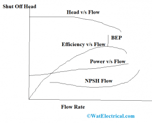
To know about the hydraulic calculations, the centrifugal pump characteristic curve is the most necessary one.

performance-curve
The components that are in this curve are:
- Efficiency curve
- Energy curve
- NPSHR v/s Flow curve
- H-Q curve
Efficiency Curve
This curve starts at ‘0’ position when there is no flow and moves linearly having the maximum at Best Efficiency position and then drops for rising flow rates.
Energy Curve
Brake Horsepower plotted in contrast to the flow rate to attain the energy curve in a centrifugal pump and it is a straight line.
NPSHR v/s Flow curve
Net Positive Suction Head Required is represented in contrast to the Flow rate. It is a flat curve.
H-Q Curve
To measure the performance of the H-Q curve, the pressure is used. The head develops shut off when the flow rate of the pump is ‘0’. Shut off is used to know the cavitation and the priming loss.
The below picture is the centrifugal pump diagram clearly explains the components involved in the device.
Cavitation and Specific Speed
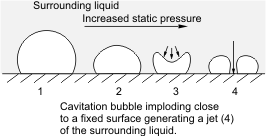
Cavitation in a centrifugal pump is an important concern to be noted to prevent pump collapse. Cavitation is the process of creation and breakdown of vapor gurgles in the liquid and this happens because of variation in pressure values. The entire performance of the pump will be affected due to cavitation. To know whether the pump got effected by cavitation or not, the symptoms are as below:
- Rise and fall in discharge pressure values
- Inconsistent power utilizations
- The decrement in the output efficiency
- Distinct crackling sounds
The effect of cavitation can be removed by lessening the length of centrifugal pumps to 4 meters ahead of the water level.

cavitation-in-centrifugal-pump
The specific speed of the centrifugal pump is described as an ideal pump corresponding to the actual pump so that when the impeller operates at the specific speed will enhance a division of volume. Centrifugal pump speed is the foremost factor to determine the performance of the device. From the performance curves, specific speed is easily measured, and the formula is
Specific speed = N. sqrt (N)/(H3/4) – measured in bep
Where ‘N’ = pump speed in RPM
‘Q’ = Flow rate calculated in litres/sec
‘H’ = Entire dynamic head (meters)
Applications of Centrifugal Pump
For many of the fluid movement activities, centrifugal pumps are considered and because these hold more prominence in multiple industries. The most general applications of centrifugal pumps are pumping water, supporting fire safety systems, water supply, hot water flow and for regulating hot water. The domains where centrifugal pumps are implemented are:
- Oil and Energy Industries for pumping mud, oil, and slurry, utilized by refining purpose and power development plants
- Centrifugal pumps are used in dirt water treating systems, municipal plants, gas systems, irrigation, and flood protection procedures.
- Used in chemical, food and pharmaceutical industries as hydrocarbons, cellulose, sugar distilling, petrochemical and in beverage production.
- Also employed in aerospace, industrial, medicinal, food and petrochemical industries in the rationales of refrigerants and cryogenics.
Advantages & Disadvantages
The benefits of a centrifugal pump are
- These pumps have no drive seals which lessens leakage complications.
- These pumps are utilized to dwell out dangerous and hazardous fluids.
- Magnetic coupling in the pump safeguards the pump from external pressures
- No chance of heat transmission
The drawbacks of the centrifugal pump are
- There might be energy loss because of magnetic coupling which develops minimal magnetic resistance.
- Intense load shows the chance to fail the pump
- When there is no functioning of pump for a long time, rust develops, and it leads to damage
- Overheating
FAQs
1). What is the impeller in the centrifugal pump?
An impeller is the revolving component of the pump and the casing section corresponds to a sealed passage that encloses the impeller.
2). Why the centrifugal pump is called centrifugal?
As the pump is operated through a force called centrifugal, it is called a centrifugal pump.
3). What is the priming of a pump?
Priming of the pump corresponds to be something ready for the operation of the device. For instance, water is necessary to start the pump functioning.
4). What are the types of pump impellers?
The basic kinds of the impeller are open, semi-open and closed.
5). How priming is done for a centrifugal pump?
Priming is done either through a separator, vacuum pump or jet pump.
As the pumping activities mainly are done in many of the works we do in our daily life, these centrifugal pumps gained the utmost importance. So, there will more advancement in the development of these devices. So, go with deep research to know more about what are other types of centrifugal pumps to be discussed and their operation?