Generally, power is the capacity to do work. In the electrical domain, electric power is the amount of energy transferred to some other form per unit of time like light, heat, etc. Mathematically, it can be defined as the product of voltage and current. Consider the DC circuits, which have only one voltage source either a voltage source or a current source, so the capacitors work as an open circuit within a steady-state whereas the inductors work like a short circuit. Here, the DC circuit performs as a resistive circuit, so the whole electric power can be dissipated in the heat form. Here, the voltage & current are in a similar phase & the whole electrical power can be given as P=V*I. So, this article gives brief information on a power triangle.
What is a Power Triangle?
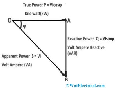
The three elements that makeup AC power, which are active power, reactive power, and apparent power, can be expressed graphically on the three sides of a right triangle, such as the impedance triangle discussed below. As shown in the below figure, the actual power P of the circuit represents the horizontal (adjacent) side, the reactive power ‘Q’ represents the vertical (opposite) side, and the hypotenuse represents the apparent power (S) generated from the power triangle.

Power Triangle
Where:
Real power P = I^2*R (that performs work) in watts, W
Reactive power Q = I^2*X or in volt-amperes reactive, VAr
Apparent power S = I2*Z in volt-amperes, VA
Z = R^2 + jX^2 in ohms
Φ = phase angle in degrees. The larger phase angle gives more reactive power
Power factor Cos(Φ) = P/S = R/Z W/VA =
Sin(Φ) = Q/S = X/Z = VAr/VA
Tan(Φ) = Q/P = X/R =VAr/W
When the voltage and current waveforms of a purely resistive circuit are in-phase with each other, the active power by the circuit is the same as the apparent power and the phase difference will be 0. It is referred to as the unity power factor.
Power factor = Cos 0° = 1
When the voltage and current waveforms of a purely reactive circuit out-phase with each other by an angle of 90 degrees, then the phase difference will be 90 degrees.
Power factor = cos 90° =0
The relationship between the apparent power, real power, and power factor of the circuit is given as
Real power P = Apparent Power (S) x Power factor
Power factor = Watts/Volt-amps
In an inductive circuit, the lagging power factor is obtained because the current lags the voltage. In a capacitive circuit, the leading power factor is obtained because the current leads the voltage. The concept of the power triangle is just a schematic representation of the phase diagram of an inductive/capacitive load connected to a source. It is obtained by the multiplication of the current I in the circuit, active current (IcosØ), and reactive current (IsinØ) by voltage V.
Voltage ‘V’ and current ‘I’ in the circuit, active current IcosØ, and reactive current IsinØ give apparent power (S), active power (P ), and reactive power (Q), respectively.
Power Triangle Formula
The graphical representation of a right-angle triangle that shows the relationship between reactive power, real/active power, and apparent power is known as the power triangle. By multiplying each component of the current, i.e. active component (Icosϕ) or reactive component (Isinϕ) to voltage V, we get a power triangle, as shown in the figure below.

Right Angle Triangle
The actual power drawn or used in an AC circuit is called true power or real power or active power. It is measured in kilowatts (kW) or MW. The power that flows back and forth, that is, the power that moves or reacts in both directions in a circuit is called reactive power.
Reactive power is measured in kilovolt-ampere reactive (kVAR) or MVAR reactive power.
The product of the square root (RMS) of voltage and current (RMS) is called apparent power. This power is measured in kVA or MVA. The next point represents the relationship between the following quantities and is illustrated by a graph called the power triangle shown above. Multiplying the active component of the current by the circuit voltage V gives the active power. This power creates torque in the motor, heat in the heater, etc. This power is measured with a device called a wattmeter. Multiply the reactive current by the circuit voltage to get reactive power. This power gives the power factor, which travels back and forth in the circuit.
Multiply the circuit current with the circuit voltage to get the apparent power. The ratio can be determined from the inverted triangle plotted as shown above i.e., the power by taking the ratio of active power to apparent power. The power factor is calculated from the above power triangle, that is the cosine angle between the voltage and current phasor, given as,
Power factor Cosφ = Active power / Apparent Power = kW/kVA
As we know, power is simply known as the product of voltage and current, but in AC circuits, except for purely resistive circuits, there is usually a phase difference between voltage and current, so VI does not represent the actual power of the circuit. The relation between the active, reactive and apparent power is given as,
(kVA) ^2 = (kW) ^2 + (kVAR) ^2
Impedance Triangle
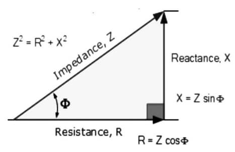
The right-angle triangle whose base, perpendicular, and hypotenuse represent the electrical resistance, reactance, and impedance, respectively is called the Impedance triangle.
This is the basic geometric representation of the impedance of a circuit.
The impedance has two components. one is resistance and the other is reactance. So it can be expressed by these two factors. The impedance of an AC circuit is Z = R+jX
Where ‘R’ is the resistance
‘X’ is the reactance.
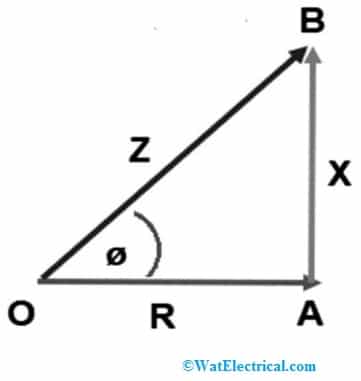
From the above expression, Z is the complex number and therefore can be expressed geometrically in the same way as a complex number. The geometric representation is shown below.

Geometric Representation
The resulting triangle OAB is called the impedance triangle. The value of the impedance Z can be easily determined from this triangle using the Pythagorean theorem. The Z impedance value is OB and can be found as
OB^2 = OA^2 + AB^2
Z^2 = R^2 + X^2
Therefore, the sum of the square of resistance and reactance is equal to the square of impedance. That is,
Z = √(R^2+X^2)
The angle of Z with R is the angle formed between the OA and OB as shown in the figure above.
tanƟ = (X/R)
Therefore, the impedance triangle is used to determine the magnitude and impedance angle, and power factor of the given circuit.
Real power, Reactive power, Active and Apparent power in AC circuits
Real Power or Active Power
In an electrical circuit, the real power (P), is also known as active or true power. Real power, measured in watts, determines the amount of power consumed by the resistive portion of the circuit. Then the active power (P) in the AC circuit is equal to the power P in the DC circuit. Thus, as in DC circuits, it is always calculated from the formula I^2 * R.
where R is the total resistive component of the circuit.
Since resistors do not create a phase difference (phase shift) between voltage and current, all usable power is transferred directly to the resistor and converted into heat, light, and operation. Then the power consumed by the resistor is the actual power, which is basically the average power of the circuit. Multiply the RMS voltage and current by the cosine of the phase angle (φ) as shown in the figure to find the corresponding actual power value.
Real power = P = I^2*R = V*I*Cosφ in Watts (W)
As there is no phase difference between the voltage and current in the resistive circuit, the phase shift between the voltage and current waveforms is also zero.
Therefore,
P = Vrms x Irms x Cosφ
Cos (0°) = 1
Hence, P = Vrms x Irms Watts
Where P = real power measured by the energy meter in Watts or kiloWatts or MegaWatts
V = RMS voltage in Volts
I= RMS current in Amps
Reactive Power (S)
The power consumed in an AC circuit that doesn’t do a useful task, but has a significant effect on the phase shift between voltage and current is called Reactive Power. Reactive power is related to the reactance created by the coil and capacitor and counteracts the effect of active power. There is no reactive power in DC circuits.
Unlike real power (P), which does all the work, reactive power (Q) creates and reduces an induced magnetic field and a capacitive electrostatic field to extract or remove the power away from a circuit, making it difficult for real power to directly supply the real power to the load or circuit.
In a magnetic field, the energy stored by the inductor tries to control the current, while the energy stored by the capacitors in the electrostatic field tries to control the voltage. As a result, the capacitor produces reactive power, and the inductor consumes reactive power. This means no real power is being consumed as they both consume power and send it back to the source. To find reactive power, multiply the RMS voltage and current by the sine of the phase angle (φ) as shown in the figure.
Reactive power Q = I^2X = VIsinφ Volt-Ampere reactive (VAr)
The phase difference of 90 degrees between the current and voltage waveforms in the pure reactance (either capacitive or inductive), multiplying VIsinφ gives the perpendicular component, which is 90 degrees out of phase with each other.
Therefore,
Q = Vrms x Irms x sinφ
Sin (90°) = 1
Q = Vrms x Irms (VAr)
Where Q = reactive power in Volt-Ampere reactive (VAr) or kilovolt-ampere reactive (kVAr) or megavolt-ampere reactiec (MVAr)
Vrms = RMS voltage in Volts
Irms = RMS current in Amps
The product of volts and amperes in 90 degrees out of phase with each other represents the reactive power. In general, there could be any phase angle between the current and voltage.
Apparent Power (S)
We know that the active power is dissipated through the resistor, and the reactive power is supplied to the reactance. This results in the current and voltage waves being out of phase due to the difference between the resistive and reactive components of the circuit. Then the mathematical relationship between real power (P) and reactive power (Q), is called the complex number. The product of the RMS voltage V applied to an alternating current circuit and the RMS value of the current flowing through this circuit is called the product of volt-amperes (VA), represented with the ‘S’, known as apparent power.
This complex power is not equal to the algebraic sum of the combined real and reactive power but is expressed as the vector sum of P and Q in volt-amperes (VA), which is the complex power represented by the power triangle. The RMS value of the volt-ampere product is generally referred to as apparent power. Because it is “obvious” that the actual power doing the work is much less, but it is the total power consumed by the circuit.
Apparent power is generated in two parts: resistive power, which is actual power or in-phase power or in watts, and the other is reactive power, which is phase power (out-of-phase) in volt-amps, so we can represent the vector sum of these two power components in the form of a power triangle. The triangle of forces P, Q, S, and θ.
Know more about Norton’s Theorem MCQs.
What is Power Triangle Impedance?
The power triangle impedance is the geometrical relationship between reactance, resistance, and impedance. It is the triangle formed by adding the resistance to the reactance.
How do you find real power?
In an electrical circuit, the real power is also referred to as active power or true power measured in Watts. It is the total power consumed by the resistive portion of the circuit. This power in DC circuits is the same as the power in AC circuits, which can be calculated by using the below formula
Real power = I^2*R
Where ‘I’ is current in Ampere
R is the resistive component.
Or Active power = VIcosφ
What is the formula for calculating power?
The maximum power that occured in an AC circuit is when the current and voltage waveforms are in phase with each other. The formula for calculating power is given as
P = V * I
Thus, this is all about an overview of the power triangle. Here is a question for you, “What are the differences between active power, apparent power, and reactive power? “